
User Manual

8. Install Tooling (A) to the inlet of the fuel transfer
pump and the end of tube assembly (1). Ensure
that Tooling (A) is secured and clear of rotating
parts.
9. Prime the fuel system. Refer to Operation and
Maintenance Manual, “Fuel System - Prime” for
the correct procedure.
10. Start the engine. Refer to Operation and
Maintenance Manual, “Starting the Engine” for the
correct procedure. Refer to steps 10.a to 10.d for
the procedure for testing the air in fuel.
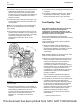
a. Run the engine a low idle speed.
b. Run the engine for 2 minutes. There should be
no air in the fuel flow through the sight tube.
Small bubbles that are spaced more than
2.5 cm (1.0 inch) are acceptable. Do not
manipulate the connections during the test for
the air in fuel.
c. The presence of large bubbles or a continuous
stream of bubbles indicates a leak.
d. Investigate potential leaks and rectify any
potential leaks in the low-pressure fuel system.
Check for leaks between the fuel tank and the
inlet of the fuel injection pump. If necessary,
replace the low-pressure fuel lines.
11. Remove Tooling (A) from the engine. Reconnect
the low-pressure lines.
12. Prime the fuel system. Refer to Operation and
Maintenance Manual, “Fuel System - Prime” for
the correct procedure.
i04676448
Finding Top Center Position
for No. 1 Piston
Table 2
Required Tools
Tool Part Number
Part Description Qty
A
(1)
27610291
Barring Device Housing
1
27610289
Gear 1
(1)
This Tool is used in the aperture for the electric starting motor.
1. Rover the valve mechanism cover. Refer to
Disassembly and Assembly, “Valve Mechanism
Cover - Remove and Install” for the correct
procedure.
2. Use Tooling (A) in order to rotate the crankshaft in
the normal direction of rotation.
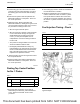
3. Rotate the crankshaft in the normal direction of
rotation until the inlet valve of number 4 cylinder
has opened and the exhaust valve of the same
cylinder has not closed completely. The piston in
the number 1 cylinder should be at the top center
position.
i05241794
Fuel Injection Timing - Check
Table 3
Required Tools
Tool Part Number
Part Description Qty
A
(1)
27610291
Barring Device Housing
1
27610289 Gear 1
B
T400152
Camshaft Timing Pin
1
(1)
This Tool is used in the aperture for the electric starting motor.
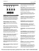
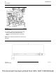
Illustration 50 g02862116
Typical example
UENR0623-02
57
Fuel System
This document has been printed from SPI2. NOT FOR RESALE