
User Manual


ECM Power Supply
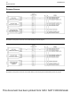
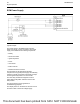
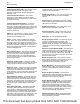
Illustration 42 g02720990
Typical example
The power supply to the ECM and the system is
drawn from the 24 V or the 12 V battery. The power
supply for the ECM has the following components:
• Battery
• Disconnect switch
• Ignition keyswitch
• Fuses
• Ground bolt
• ECM connector
• Machine interface connector
The schematic for the ECM shows the main
components for a typical power supply circuit. Battery
voltage is normally connected to the ECM. The input
from the ignition keyswitch turns on the ECM.
The main relay will remain energized for a time
period after the keyswitch has been turned to the
OFF position.
The wiring harness can be bypassed for
troubleshooting purposes.
The display screen on the electronic service tool can
be used in order to check the voltage supply.
46 UENR0623-02
Engine Operation
This document has been printed from SPI2. NOT FOR RESALE