
User Manual
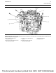
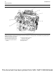
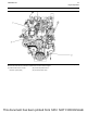
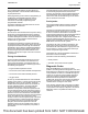

Sensor Locations for the Clean
Emissions Module
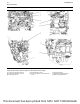
Illustration 32 g02738216
Typical view of the sensor locations
(18) Diesel Oxidation Catalyst (DOC) inlet
temperature sensor
(19) Diesel Particulate Filter (DPF) inlet
temperature sensor
(20) Inlet connection for the DPF differential
pressure sensor
(21) Outlet connection for the DPF
differential pressure sensor
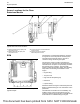
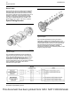
ECM
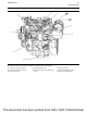
Illustration 33 g02722357
Typical example
The Electronic Control Module (ECM) (1) functions
as a governor and a computer for the fuel system.
The ECM receives signals from the sensors to
control the timing and the engine speed.
The electronic system consists of the ECM, the
engine sensors, and inputs from the parent machine.
The ECM is the computer. The personality module is
the software for the computer. The personality
module contains the operating maps. The operating
maps define the following characteristics of the
engine:
• Engine rating
• Torque curves
• High and low idle speed (rpm)
• Emissions
• Injection timing
Passwords restrict changes to authorized personnel.
Refer to Troubleshooting for more information on the
passwords.
The ECM has an excellent record of reliability. Any
problems in the system are most likely to be the
connectors and the wiring harness. The ECM should
be the last item in troubleshooting the engine.
38 UENR0623-02
Engine Operation
This document has been printed from SPI2. NOT FOR RESALE