
User Manual
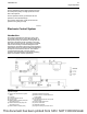
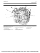
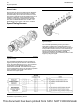

Illustration 29 g02737956
A typical example of sensors and electrical connector locations on the right side of the 854E-E34TA (model JR) and
854F-E34TA (model JV) engines
(9) Inlet manifold air pressure and
temperature sensor
(10) Connector for the temperature sensor
(NOx Reduction System)
(11) Pressure sensor (NOx Reduction
System)
(12) Exhaust gas valve for the NOx
Reduction System (NRS)
(13) Wastegate regulator
(14) Oxygen sensor
UENR0623-02 35
Engine Operation
This document has been printed from SPI2. NOT FOR RESALE