
User Manual
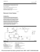
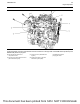
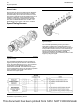

The fuel manifold (2) stores high-pressure fuel from
the fuel injection pump. The high-pressure fuel will
flow to the injectors.
The fuel pressure sensor (3) measures the fuel
pressure in the fuel manifold (2).
The pressure relief valve (1) will prevent the fuel
pressure from getting too high.
i06718976
Electronic Control System
Introduction
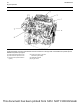
The engine is designed for electronic control. The
engine has an Electronic Control Module (ECM), a
fuel injection pump, and electronic unit injectors. All
these items are electronically controlled. There are
also various engine sensors. The engine is equipped
with an electronically controlled wastegate for the
turbocharger. The ECM controls the engine operating
parameters through the software within the ECM and
the inputs from the various sensors. The software
contains parameters that control the engine
operation. The parameters include all the operating
maps and customer-selected parameters.
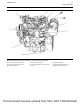
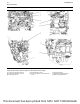
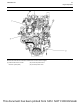
Illustration 26 g02889596
Typical example
(1) Valve for the NOx Reduction System
(NRS)
(2) Air cleaner
(3) Air inlet temperature sensor
(4) Oxygen sensor
(5) Diesel Oxidation Catalyst (DOC) inlet
temperature sensor
(6) Diesel Particulate Filter (DPF) inlet
temperature sensor
(7) Diesel Oxidation Catalyst (DOC)
(8) Diesel Particulate Filter (DPF)
(9) Exhaust Cooler for the NOx Reduction
System (NRS)
(10) Turbocharger
(11) DPF differential pressure sensor (wall
flow DPF only)
(12) Engine intake throttle valve
(13) Air-to-air aftercooler
(14) Wastegate regulator
(15) Engine exhaust gas pressure sensor
UENR0623-02 31
Engine Operation
This document has been printed from SPI2. NOT FOR RESALE