
User Manual

High Pressure Fuel System
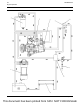
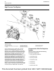
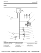
Illustration 19 g02493876
Typical example
(1) Fuel injection pump
(2) Suction control valve for the fuel injection
pump
(3) Pressure relief valve
(4) Fuel manifold (rail)
(5) Electronic unit injector
(6) Fuel pressure sensor
(7) Fuel transfer pump
The fuel injection pump (1) feeds fuel to the high-
pressure fuel manifold (rail) (4). The fuel is at a
pressure of up to 160 MPa (23200 psi). A pressure
sensor (6) in the high-pressure fuel manifold (rail) (4)
monitors the fuel pressure in the high-pressure fuel
manifold (rail). The ECM controls a suction control
valve (2) in the fuel injection pump in order to
maintain the actual pressure in the high-pressure fuel
manifold at the desired level. The high-pressure fuel
is continuously available at each injector (5). The
ECM determines the correct time for activation of the
correct electronic unit injector (5) which allows fuel to
be injected into the cylinder. The leakoff fuel from
each injector passes through an external pipe above
the electronic unit injectors. The leakoff fuel then
flows to a connector block on the left-hand side of the
engine. A pipe is connected from the connector block
in order to return the leakoff fuel to the fuel tank.
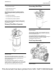
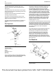
Components of the Fuel Injection
System
The fuel injection system has the following
mechanical components:
• Primary filter/water separator
• Fuel transfer pump
• Secondary fuel filter
• Fuel injection pump
• Fuel injectors
• Fuel manifold
• Pressure relief valve
26 UENR0623-02
Engine Operation
This document has been printed from SPI2. NOT FOR RESALE