
User Manual
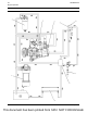
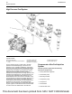
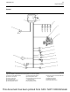

Typical example
(1) Primary fuel filter
(2) Secondary fuel filter
(3) Fuel Injection Pump
(4) Fuel transfer pump
(5) Fuel manifold (rail)
(6) Pressure relief valve
(7) Electronic unit injector
(8) Manifold connector
(9) Fuel cooler (if equipped)
(A) Fuel tank
Fuel is drawn from the fuel tank to the 10 micron
primary fuel filter and a water separator. The fuel then
flows to the fuel transfer pump. The fuel transfer
pump is part of the fuel injection pump.
Fuel then flows from the fuel transfer pump to the 4
micron secondary fuel filter. Fuel flows from the
secondary fuel filter to the fuel injection pump.
At the fuel injection pump, the fuel is pumped at an
increased pressure of up to 160 MPa (23200 psi)
fuel manifold (rail).
Fuel that has too high a pressure from the fuel
manifold (rail) returns through the pressure relief
valve to the return line. Fuel that is leak off from the
electronic unit injectors flows to the return line. The
fuel may then flow through a fuel cooler (if equipped)
on the way back to the fuel tank.
UENR0623-02 25
Engine Operation
This document has been printed from SPI2. NOT FOR RESALE