
User Manual
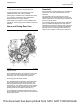
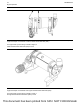

The camshaft has two camshaft lobes for each
cylinder. The lobes operate either the inlet valve or
the exhaust valve. As the camshaft turns, lobes on
the camshaft cause the lifter to move the pushrod up
and down. Upward movement of the pushrod against
rocker arm results in a downward movement.
This action opens a pair of valves which compresses
the valve springs. When the camshaft has rotated to
the peak of the lobe, the valves are fully open. When
the camshaft rotates further, the two valve springs
under compression start to expand. The valve stems
are under tension of the springs. The stems are
pushed upward. The continued rotation of the
camshaft causes the rocker arm, the pushrods and
the lifters to move downward until the lifter reaches
the bottom of the lobe. The valves are now closed.
The cycle is repeated for all the valves on each
cylinder.
The rocker arm incorporates a hydraulic lash adjuster
which removes valve lash from the valve mechanism.
The hydraulic lash adjuster uses engine lubricating
oil to compensate for wear of system components so
that no service adjustment of valve lash is needed.
The engine lubricating oil enters the hydraulic lash
adjuster through a non-return valve. The engine
lubricating oil increases the length of the hydraulic
lash adjuster until all valve lash is removed. If the
engine is stationary for a prolonged period the valve
springs will cause the hydraulic lash adjuster to
shorten so that when the engine is started engine
valve lash is present for the first few seconds.
After cranking restores oil pressure the hydraulic lash
adjuster increases in length and removes the valve
lash. When load is removed from a hydraulic lash
adjuster during service work by the removal of the
rocker shaft the hydraulic lash adjuster increases in
length to the maximum extent. Refer to Systems
Operation, Testing and Adjusting, “Position the Valve
Mechanism Before Maintenance Procedures” for the
correct procedure.
During reassembly of the rocker shaft the engine
must be put into a safe position to avoid engine
damage. After load is imposed on the lifters by
reassembling the rocker assembly, the engine must
be left in safe position for a safe period until the lifters
have reduced to the correct length. Refer to
Disassembly and Assembly, “Rocker Shaft and
Pushrod - Install” for the correct procedure.
i05242096
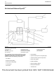
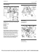
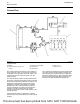
Clean Emissions Module
To meet current emissions legislation requirements, a
small amount of certain chemical compounds that are
emitted by the engine must not be allowed to enter
the atmosphere. The Clean Emissions Module
(CEM) that is installed to the engine is designed to
convert these chemical compounds into less harmful
compounds.
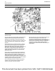
The Engine Aftertreatment System for the engine
consists of the following components.
• Diesel Oxidation Catalyst (DOC)
• Diesel Particulate Filter (DPF)
The Diesel Oxidation Catalyst (DOC) oxidizes the
carbon monoxide and the hydrocarbons that are not
burnt in the exhaust gas into carbon dioxide and
water. The Diesel Oxidation Catalyst (DOC) is a
through flow device that will continue to operate
during all normal engine operating conditions.
The Diesel Particulate Filter (DPF) collects all solid
particulate matter in the exhaust gas.
The solid particulate matter that is collected by the
DPF consists of soot (carbon) from incomplete
combustion of the fuel and inorganic ash from the
combustion of any oil in the cylinder.
UENR0623-02 17
Engine Operation
This document has been printed from SPI2. NOT FOR RESALE