
User Manual

When the load on the engine increases, more fuel is
injected into the cylinders. The combustion of this
additional fuel produces more exhaust gases. The
additional exhaust gases cause the turbine and the
compressor wheels of the turbocharger to turn faster.
As the compressor wheel turns faster, air is
compressed to a higher pressure and more air is
forced into the cylinders. The increased flow of air
into the cylinders allows the fuel to be burnt with
greater efficiency. The more efficient burning of fuel
produces more power.
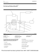
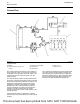
A wastegate is installed on the turbine housing of the
turbocharger. The wastegate is a valve that allows
exhaust gas to bypass the turbine wheel of the
turbocharger. The operation of the wastegate is
dependent on the pressurized air (boost pressure)
from the turbocharger compressor. The boost
pressure acts on a diaphragm. The diaphragm is
spring loaded in the wastegate actuator which varies
the amount of exhaust gas that flows into the turbine.
The wastegate regulator (15) is controlled by the
engine electronic control module (ECM). The ECM
uses inputs from a number of engine sensors to
determine the optimum boost pressure. This will
achieve the best exhaust emissions and fuel
consumption at any given engine operating condition.
The ECM controls the wastegate regulator, that
regulates the boost pressure to the wastegate
actuator.
When high boost pressure is needed for the engine
performance, a signal is sent from the ECM to the
wastegate regulator. This causes high pressure in
the inlet manifold to act on the diaphragm within the
wastegate actuator (13). The actuating rod (14) acts
upon the actuating lever to close the valve in the
wastegate. When the valve in the wastegate is
closed, more exhaust gas is able to pass over the
turbine wheel. This results in an increase in the
speed of the turbocharger.
When low boost pressure is needed for the engine
performance, a signal is sent from the ECM to the
wastegate regulator. This causes high pressure in
the air inlet pipe (12) to act on the diaphragm within
the wastegate actuator (13). The actuating rod (14)
acts upon the actuating lever to open the valve in the
wastegate. When the valve in the wastegate is
opened, more exhaust gas from the engine is able to
bypass the turbine wheel, resulting in a decrease in
the speed of the turbocharger.
The shaft that connects the turbine to the compressor
wheel rotates in bearings (4) and (6). The bearings
require oil under pressure for lubrication and cooling.
The oil that flows to the lubricating oil inlet port (5)
passes through the center of the turbocharger which
retains the bearings. The oil exits the turbocharger
from the lubricating oil outlet port (10) and returns to
the oil pan.
Crankcase Breather
NOTICE
The crankcase breather gases are part of the en-
gines measured emissions output. Any tampering
with the breather system could invalidate the engines
emissions compliance.
The crankcase breather has a centrifugal separator.
The centrifugal separator has a special coating.
Engine oil that has been separated from the breather
gas is returned to the timing case. The crankcase
breather is driven by the shaft of the fuel injection
pump.
A heated connection may be installed on the pipe for
the crankcase breather. The purpose of the heated
connection is to prevent the formation of ice in cold
climates, that could lead to an obstruction of the pipe.
Valve System Components
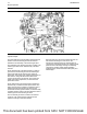
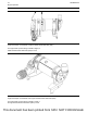
Illustration 14 g02720989
Valve system components
(1) Rocker arm
(2) Pushrod
(3) Lifter
(4) Camshaft
The valve system components control the flow of
inlet air into the cylinders during engine operation.
The valve system components also control the flow
of exhaust gases out of the cylinders during engine
operation.
The crankshaft gear drives the camshaft gear. The
camshaft must be timed to the crankshaft in order to
get the correct relation between the piston movement
and the valve movement.
16 UENR0623-02
Engine Operation
This document has been printed from SPI2. NOT FOR RESALE