
User Manual

Turbocharger
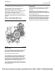
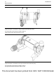
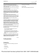
Illustration 11 g00302786
Typical example of a cross section of a turbocharger
(1) Air intake
(2) Compressor housing
(3) Compressor wheel
(4) Bearing
(5) Oil inlet port
(6) Bearing
(7) Turbine housing
(8) Turbine wheel
(9) Exhaust outlet
(10) Oil outlet port
(11) Exhaust inlet
The turbocharger is mounted on the outlet of the
exhaust manifold. The exhaust gas from the exhaust
manifold enters the exhaust inlet (11) and passes
through the turbine housing (7) of the turbocharger.
Energy from the exhaust gas causes the turbine
wheel (8) to rotate. The turbine wheel is connected
by a shaft to the compressor wheel (3).
As the turbine wheel rotates, the compressor wheel
is rotated. The rotation of the compressor wheel
causes the intake air to be pressurized through the
compressor housing (2) of the turbocharger.
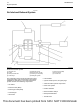
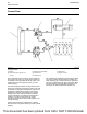
Illustration 12 g02720975
Typical example
(12) Line (boost pressure)
(13) Wastegate actuator
(14) Actuating lever
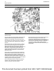
Illustration 13 g02720981
Typical example
(15) Wastegate regulator
UENR0623-02 15
Engine Operation
This document has been printed from SPI2. NOT FOR RESALE