
User Manual


The port for the inlet valve is on the top of the cylinder
head. The port for the exhaust valve is on the right
side of the cylinder head. The valve stems move in
valve guides that are pressed into the cylinder head.
There is a renewable oil seal that fits over the top of
the valve guide. The valve seats and the valve guides
are replaceable.
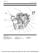
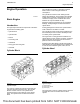
Pistons, Rings, and Connecting
rods
Illustration 6 g02859336
Typical example
The pistons (3) have a Quiescent combustion
chamber in the top of the piston in order to provide an
efficient mix of fuel and air. The piston pin (9) is off-
center in order to reduce the noise level. The position
pin (9) is retained in the correct position by two
circlips (8).
The pistons (3) have two compression rings (1) and
an oil control ring (2). The groove for the top ring has
a hard metal insert in order to reduce wear of the
groove. The piston skirt has a coating of graphite in
order to reduce the risk of seizure when the engine is
new.
The correct piston height is important in order to
ensure that the piston does not contact the cylinder
head. The correct piston height also ensures the
efficient combustion of fuel which is necessary in
order to conform to requirements for emissions.
The connecting rods (4) are machined from forged
steel. The connecting rods have bearing caps (6) that
are fracture split. The bearing caps (6) on fracture
split connecting rods (4) are retained with bolts (7).
Connecting rods with bearing caps that are fracture
split have the following characteristics:
• The splitting produces an accurately matched
surface on each side of the fracture for improved
strength.
• The correct connecting rod must be installed with
the correct bearing cap. Each connecting rod and
bearing cap have a unique serial number. When a
connecting rod is assembled the serial numbers
for the connecting rod and bearing cap must
match.
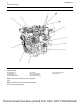
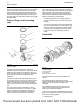
Crankshaft
Illustration 7 g02841976
Typical example
(1) Crankshaft gear
(2) Crankshaft
(3) Crankshaft thrust washers
The crankshaft can be a spheroidal graphite iron
casting.
The crankshaft has five main journals. Thrust
washers are installed on both sides of number 3 main
bearing in order to control the end play of the
crankshaft.
The crankshaft changes the linear energy of the
pistons and connecting rods into rotary torque in
order to power external equipment.
A gear at the front of the crankshaft drives the timing
gears. The crankshaft gear turns the idler gear which
then turns the following gears:
• Camshaft gear
10 UENR0623-02
Engine Operation
This document has been printed from SPI2. NOT FOR RESALE