UENR0623-02 (en-us) June 2016 Systems Operation Testing and Adjusting 854E-E34TA, 854F-E34T and 854FE34TA Industrial Engines JR (Engine) JS (Engine) JT (Engine) JV (Engine) This document has been printed from SPI2.
Important Safety Information Most accidents that involve product operation, maintenance and repair are caused by failure to observe basic safety rules or precautions. An accident can often be avoided by recognizing potentially hazardous situations before an accident occurs. A person must be alert to potential hazards. This person should also have the necessary training, skills and tools to perform these functions properly.
UENR0623-02 3 Table of Contents Table of Contents Systems Operation Section General Information Introduction ..........................................................4 Engine Operation Basic Engine.........................................................9 Air Inlet and Exhaust System ...............................12 Clean Emissions Module .....................................17 Cooling System ..................................................19 Lubrication System ........................................
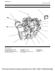
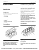
UENR0623-02 General Information Systems Operation Section General Information i06718957 Introduction The following model views show a typical industrial engine. Due to individual applications, your engine may appear different from the illustrations. This document has been printed from SPI2.
UENR0623-02 General Information Illustration 1 g02317613 Typical example (1) Clean Emissions Module (CEM) (2) Oil gauge (Dipstick) (3) Electronic Control Module (ECM) (4) Air inlet connection from charge cooler (5) Coolant outlet connection (6) Air intake from air filter (7) Alternator (8) Coolant intake connection (9) Air outlet connection from turbocharger (10) Turbocharger (11) Oil drain plug (12) Starting motor (13) Flywheel housing (14) Flywheel This document has been printed from SPI2.
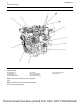
UENR0623-02 General Information Illustration 2 g03343018 Typical example (15) Front lifting eye (16) Oil filler cap (17) Rear lifting eyes (18) Secondary fuel filter (19) Oil filter (20) Fuel priming pump (21) Primary fuel filter (22) Fuel injection pump (23) Crankcase breather (24) Water pump Note: The primary fuel filter (21) may be supplied loose. Note: The Electronic Control Module (ECM) (3) will be mounted to the application. This document has been printed from SPI2.
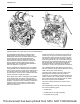
UENR0623-02 General Information Illustration 3 g06082892 Typical example of an engine with top mounted aftertreatment The 854E-E34TA, 854F-E34T, and 854F-E34TA diesel engines are electronically controlled. The 854E-E34TA, 854F-E34T, and 854F-E34TA engines have an Electronic Control Module (ECM) that receives signals from the fuel injection pump and other sensors to control the electronic unit injector. The fuel injection pump supplies fuel to the fuel manifold (Rail).
UENR0623-02 General Information • the accessory drive gear • the fuel injection pump gear The camshaft runs at half the rpm of the crankshaft. The fuel injection pump runs at one and a half times the speed as the crankshaft. The fuel injection pump that is installed on the left side of the engine is gear-driven from the timing case. The internal fuel transfer pump is driven by the fuel injection pump. The fuel transfer pump draws low-pressure fuel from the primary fuel filter.
UENR0623-02 9 Engine Operation Engine Operation The cylinders are honed to a specially controlled finish in order to ensure long life and low oil consumption. i04169549 Basic Engine The cylinder block has five main bearings which support the crankshaft. Thrust washers are installed on both sides of number 3 main bearing in order to control the end play of the crankshaft. The thrust washers can only be installed one way. Passages supply the lubrication for the crankshaft bearings.
UENR0623-02 Engine Operation The port for the inlet valve is on the top of the cylinder head. The port for the exhaust valve is on the right side of the cylinder head. The valve stems move in valve guides that are pressed into the cylinder head. There is a renewable oil seal that fits over the top of the valve guide. The valve seats and the valve guides are replaceable. Pistons, Rings, and Connecting rods The connecting rods (4) are machined from forged steel.
UENR0623-02 11 Engine Operation • Fuel injection pump and fuel transfer pump Camshaft Lip type seals are used on both the front of the crankshaft and the rear of the crankshaft. The engine has a single camshaft. The camshaft is made of cast iron. The camshaft lobes are chill hardened. A timing ring is installed to the crankshaft. The timing ring is used by the ECM in order to measure the engine speed and the engine position. The camshaft is driven at the front end.
UENR0623-02 Engine Operation i04174031 Air Inlet and Exhaust System Illustration 9 g02720982 Air inlet and exhaust system (1) Aftercooler core (2) Air filter (3) Diesel particulate filter (4) Turbocharger (5) Wastegate actuator (6) Boost pressure chamber (7) Exhaust gas valve (NRS) (8) Wastegate regulator The components of the air inlet and exhaust system control the quality of air and the amount of air that is available for combustion.
UENR0623-02 13 Engine Operation Air is drawn in through the air cleaner into the air inlet of the turbocharger by the turbocharger compressor wheel. The air is compressed to a pressure of about 150 kPa (22 psi) and the compression heats the air to about 120° C (248° F) before the air is forced to the aftercooler. As the air flows through the aftercooler the temperature of the compressed air lowers to about 55° C (131° F). Cooling of the inlet air assists the combustion efficiency of the engine.
UENR0623-02 Engine Operation Illustration 10 g02720984 Typical example The NOx Reduction System (NRS) operates with the transfer of the hot exhaust gas from the exhaust manifold to the assembly of the exhaust gas valve. The assembly of the exhaust gas valve consists of an exhaust gas valve and an electronically controlled actuator. As the electronically controlled actuator (7) starts to open the flow of exhaust gas from the exhaust gas valve mixes with the air flow from the charge air aftercooler.
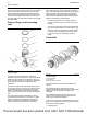
UENR0623-02 15 Engine Operation Turbocharger Illustration 12 Illustration 11 g00302786 Typical example of a cross section of a turbocharger (1) Air intake (2) Compressor housing (3) Compressor wheel (4) Bearing (5) Oil inlet port (6) Bearing (7) Turbine housing (8) Turbine wheel (9) Exhaust outlet (10) Oil outlet port (11) Exhaust inlet g02720975 Typical example (12) Line (boost pressure) (13) Wastegate actuator (14) Actuating lever The turbocharger is mounted on the outlet of the exhaust manifold.
UENR0623-02 Engine Operation When the load on the engine increases, more fuel is injected into the cylinders. The combustion of this additional fuel produces more exhaust gases. The additional exhaust gases cause the turbine and the compressor wheels of the turbocharger to turn faster. As the compressor wheel turns faster, air is compressed to a higher pressure and more air is forced into the cylinders. The increased flow of air into the cylinders allows the fuel to be burnt with greater efficiency.
UENR0623-02 17 Engine Operation The camshaft has two camshaft lobes for each cylinder. The lobes operate either the inlet valve or the exhaust valve. As the camshaft turns, lobes on the camshaft cause the lifter to move the pushrod up and down. Upward movement of the pushrod against rocker arm results in a downward movement. This action opens a pair of valves which compresses the valve springs. When the camshaft has rotated to the peak of the lobe, the valves are fully open.
UENR0623-02 Engine Operation Illustration 15 g03343187 A typical example of a CEM with a wall flow Diesel Particulate Filter (DPF) For engines with a power rating of 55 kW or higher, a wall flow Diesel Particulate Filter (DPF) is used. Illustration 16 g03343192 A typical example of a CEM with a through flow Diesel Particulate Filter (DPF) For engines with a power rating of 55 kW or lower, a through flow Diesel Particulate Filter (DPF) is used. This document has been printed from SPI2.
UENR0623-02 19 Engine Operation The wall flow Diesel Particulate Filter (DPF) is designed to contain all the ash up to the ash service interval. Refer to Operation and Maintenance Manual for more information. No ash service is required for the through flow Diesel Particulate Filter (DPF). • Exhaust gas cooler (NRS) • Cylinder head • Water temperature regulator (thermostat) The engine aftertreatment system is designed to oxidize the soot in the DPF at the same rate as the soot is produced by the engine.
UENR0623-02 Engine Operation Coolant Flow Illustration 17 g02847496 Typical example (1) Radiator (2) Water temperature regulator and housing (3) Exhaust gas cooler (NRS) (4) Cylinder head (5) Cylinder block The coolant flows from the bottom of the radiator (1) to the engine oil cooler (7). The engine oil cooler (7) is installed on the right-hand side of the engine. The coolant flows from the engine oil cooler (7) to the water pump (6).
UENR0623-02 21 Engine Operation The coolant then flows into the housing of the water temperature regulator (2). If the water temperature regulator is closed, the coolant goes directly through a bypass to the inlet side of the water pump. If the water temperature regulator is open, and the bypass is closed then the coolant flows to the top of the radiator (1). The hub of the idler gear is lubricated by oil from the oil gallery. The timing gears are lubricated by the splash from the oil.
UENR0623-02 Engine Operation The alternator converts the mechanical energy and the magnetic field into alternating current and voltage. This conversion is done by rotating a direct current electromagnetic field on the inside of a threephase stator. The electromagnetic field is generated by electrical current flowing through a rotor. The stator generates alternating current and voltage. The alternating current is changed to direct current by a three-phase, full-wave rectifier.
UENR0623-02 23 Engine Operation For more information, refer to Operation and Maintenance Manual, “Fluid Recommendations”. i04175249 Fuel Injection Introduction This document has been printed from SPI2.
UENR0623-02 Engine Operation Illustration 18 g02511124 This document has been printed from SPI2.
UENR0623-02 25 Engine Operation Typical example (1) Primary fuel filter (2) Secondary fuel filter (3) Fuel Injection Pump (4) Fuel transfer pump (5) Fuel manifold (rail) (6) Pressure relief valve (7) Electronic unit injector (8) Manifold connector (9) Fuel cooler (if equipped) (A) Fuel tank Fuel is drawn from the fuel tank to the 10 micron primary fuel filter and a water separator. The fuel then flows to the fuel transfer pump. The fuel transfer pump is part of the fuel injection pump.
UENR0623-02 Engine Operation High Pressure Fuel System Illustration 19 g02493876 Typical example (1) Fuel injection pump (2) Suction control valve for the fuel injection pump (3) Pressure relief valve (4) Fuel manifold (rail) (5) Electronic unit injector The fuel injection pump (1) feeds fuel to the highpressure fuel manifold (rail) (4). The fuel is at a pressure of up to 160 MPa (23200 psi).
UENR0623-02 27 Engine Operation Secondary Fuel Filter • Fuel pressure sensor • Fuel temperature sensor • Water in fuel sensor The following list contains examples of both service and repairs when you must prime the system: • A fuel filter is changed. • A low-pressure fuel line is replaced. • The fuel injection pump is replaced. For the correct procedure to prime the fuel system, refer to Systems Operation, Testing and Adjusting, “Fuel System - Prime”.
UENR0623-02 Engine Operation The fuel pump assembly consists of a low-pressure transfer pump and a high-pressure fuel injection pump. The pump assembly is driven from a gear in the front timing case at one a half times the engine speed. The fuel injection pump (1) has one plunger that are driven by a camshaft. The stroke of the plunger is fixed but the volume of fuel that is provided by the fuel injection pump is controlled by the suction control valve.
UENR0623-02 29 Engine Operation Control Illustration 23 g02511078 Typical example of the electrical control system for the fuel system (1) Electronic Control Module (ECM) (2) Electronic unit injectors (3) Suction control valve (4) Fuel injection pump (5) Crankshaft position sensor (6) Camshaft position sensor (7) Coolant temperature sensor (8) Fuel temperature sensor (9) Inlet manifold air temperature and pressure sensor (10) Oil pressure switch (11) Fuel pressure sensor (12) Pressure sensor for the
UENR0623-02 Engine Operation The ECM determines the quantity, timing, and pressure of the fuel in order to be injected into the fuel injector. The ECM uses input from the sensors on the engine. These sensors include the speed/timing sensors and the pressure sensors. The ECM controls the timing and the flow of fuel by actuating the injector solenoid. The amount of fuel is injected is a function of fuel pressure in the fuel manifold and the duration of the signal to the injector solenoid.
UENR0623-02 31 Engine Operation The fuel manifold (2) stores high-pressure fuel from the fuel injection pump. The high-pressure fuel will flow to the injectors. The fuel pressure sensor (3) measures the fuel pressure in the fuel manifold (2). The pressure relief valve (1) will prevent the fuel pressure from getting too high. i06718976 Electronic Control System Introduction The engine is designed for electronic control.
UENR0623-02 Engine Operation (16) Engine exhaust gas temperature sensor (17) Crankshaft speed/timing sensor (18) Camshaft speed/timing sensor (19) Electronic unit injectors (20) Fuel injection pump (21) Fuel pressure sensor (22) Oil pressure switch (23) Coolant temperature sensor (24) ECM (25) Engine (26) Glow plugs (27) Glow plug Control Unit (GCU) (28) Primary fuel filter with water-in-fuel sensor (29) Inlet manifold air temperature/pressure sensor (30) Secondary fuel filter with fuel temperature
UENR0623-02 33 Engine Operation Illustration 27 g03343020 Sensors and electrical connector locations on the left side of the engine (1) 10-pin engine interface connector (2) 62-pin engine interface connector (3) Fuel pressure sensor (4) Fuel temperature sensor (5) Inlet metering valve for the fuel injection pump (6) Oil pressure switch (7) Crankshaft speed/timing sensor (8) Water In Fuel (WIF) sensor This document has been printed from SPI2.
UENR0623-02 Engine Operation Illustration 28 g03343021 Close up views of the sensor locations on the left side of the engine (1) 10-pin engine interface connector (2) 62-pin engine interface connector (3) Fuel pressure sensor (4) Fuel temperature sensor (5) Inlet metering valve for the fuel injection pump (6) Oil pressure switch (7) Crankshaft speed/timing sensor (8) Water In Fuel (WIF) sensor This document has been printed from SPI2.
UENR0623-02 35 Engine Operation Illustration 29 g02737956 A typical example of sensors and electrical connector locations on the right side of the 854E-E34TA (model JR) and 854F-E34TA (model JV) engines (9) Inlet manifold air pressure and temperature sensor (10) Connector for the temperature sensor (NOx Reduction System) (11) Pressure sensor (NOx Reduction System) (12) Exhaust gas valve for the NOx Reduction System (NRS) (13) Wastegate regulator (14) Oxygen sensor This document has been printed from
UENR0623-02 Engine Operation Illustration 30 g03356014 A typical example of sensors and electrical connector locations on the right side of the 854F-E34T (model JS) and 854F-E34T (model JT) engines (15) Inlet manifold temperature sensor (16) Inlet manifold air pressure sensor (17) Pressure sensor (NOx Reduction System) (18) Exhaust gas valve for the NOx Reduction System (NRS) (19) Wastegate regulator (20) Oxygen sensor This document has been printed from SPI2.
UENR0623-02 37 Engine Operation Illustration 31 g03356021 Sensors and electrical connection locations on the front of the engine. (21) Intake throttle valve for the NOx Reduction System (NRS) (22) Coolant temperature sensor (23) Camshaft position sensor This document has been printed from SPI2.
UENR0623-02 Engine Operation Sensor Locations for the Clean Emissions Module Illustration 32 g02738216 Typical view of the sensor locations (18) Diesel Oxidation Catalyst (DOC) inlet temperature sensor (19) Diesel Particulate Filter (DPF) inlet temperature sensor (20) Inlet connection for the DPF differential pressure sensor (21) Outlet connection for the DPF differential pressure sensor ECM The Electronic Control Module (ECM) (1) functions as a governor and a computer for the fuel system.
UENR0623-02 39 Engine Operation The programmable software contains all the fuel setting information. The information determines the engine performance. Flash programming is the method of programming or updating the programmable software. Refer to Troubleshooting, “Flash Programming” for the instructions on the flash programming of the programmable software. The ECM adjusts injection timing and fuel pressure for the best engine performance, the best fuel economy, and the best control of exhaust emissions.
UENR0623-02 Engine Operation Event Codes Event Codes are used to indicate that the ECM has detected an abnormal engine operating condition. The ECM will log the occurrence of the event code. This does not indicate an electrical malfunction or an electronic malfunction. If the temperature of the coolant in the engine is higher than the permitted limit, then the ECM will detect the condition. The ECM will then log an event code for the condition.
UENR0623-02 41 Engine Operation When the engine is cranking, the ECM uses the signal from the speed/timing sensor on the camshaft. When the engine is running the ECM uses the signal from the speed/timing sensor on the crankshaft. This speed/timing sensor is the primary source of the engine position. This document has been printed from SPI2.
UENR0623-02 Engine Operation Pressure Sensors Illustration 37 g03360401 Schematic for the pressure sensors for the 854E-E34TA (model JR) engine Illustration 38 g03360409 Schematic for the pressure sensors for the 854F-E34T (model JS) engine and 854F-E34T (model JT) engine This document has been printed from SPI2.
UENR0623-02 43 Engine Operation Illustration 39 g03360405 Schematic for the DPF differential pressure sensor for the 854E-E34TA (model JR) engine and 854F-E34T (model JS) engine The boost pressure sensor is an active sensor. The boost pressure sensor provides the ECM with a measurement of inlet manifold pressure to control the air/fuel ratio. This will reduce the engine smoke during transient conditions. An engine oil pressure switch is installed to the engine.
UENR0623-02 Engine Operation Temperature Sensors Illustration 40 g03360451 Schematic for the temperature sensors for the 854E-E34TA (model JR) engine This document has been printed from SPI2.
UENR0623-02 45 Engine Operation Illustration 41 g03360457 Schematic for the temperature sensors for the 854F-E34T (model JS) engine and 854F-E34T (model JT) engine The air inlet temperature sensor and the coolant temperature sensor are passive sensors. Each sensor provides a temperature input to the ECM. The ECM controls following operations: • Fuel delivery • The solenoid for the wastegate • Diagnostic connector • Electronic unit injectors The glow plugs are powered directly from the battery.
UENR0623-02 Engine Operation ECM Power Supply Illustration 42 g02720990 Typical example The power supply to the ECM and the system is drawn from the 24 V or the 12 V battery. The power supply for the ECM has the following components: • Battery • Disconnect switch • Ignition keyswitch • Fuses • Ground bolt • ECM connector • Machine interface connector The schematic for the ECM shows the main components for a typical power supply circuit. Battery voltage is normally connected to the ECM.
UENR0623-02 47 Engine Operation Power Supply for the Pressure Sensors Illustration 43 g03360401 Schematic for the pressure sensors for the 854E-E34TA (model JR) engine Illustration 44 g03360409 Schematic for the pressure sensors for the 854F-E34T (model JS) engine and 854F-E34T (model JT) engine This document has been printed from SPI2.
UENR0623-02 Engine Operation Illustration 45 g03360405 Schematic for the DPF differential pressure sensor for the 854E-E34TA (model JR) engine and 854F-E34T (model JS) engine The ECM supplies 5 DC volts through the ECM connector to each sensor. The power supply is protected against short circuits. A short in a sensor or a wiring harness will not cause damage to the ECM. This document has been printed from SPI2.
UENR0623-02 49 Engine Operation Power supply for the Glow plugs Illustration 46 g02381262 Typical example The ECM supplies 5 DC volts through the ECM connector to the glow plug control unit. The glow plug control unit controls the glow plugs. i04802048 Glossary of Electronic Control Terms top center position in the normal direction of rotation. Boost Pressure – The difference between the turbocharger outlet pressure and atmospheric pressure is commonly referred to as boost pressure.
UENR0623-02 Engine Operation Component Identifier (CID) – The CID is a number that identifies the specific component of the electronic control system that has experienced a diagnostic code. Coolant Temperature Sensor – The coolant temperature sensor detects the engine coolant temperature for all normal operating conditions and for engine monitoring. Customer Specified Parameters – A customer specified parameter is a parameter that can be changed in the ECM with the Electronic Service Tool.
UENR0623-02 51 Engine Operation Event Code – An event code may be activated in order to indicate an abnormal engine operating condition. These codes usually indicate a mechanical problem instead of an electrical system problem. Failure Mode Identifier (FMI) – This identifier indicates the type of failure that is associated with the component. The FMI has been adopted from the SAE practice of J1587 diagnostics. The FMI follows the parameter identifier (PID) in the descriptions of the fault code.
UENR0623-02 Engine Operation Harness – The harness is the bundle of wiring (loom) that connects all components of the electronic system. Open Circuit – An open circuit is a condition that is caused by an open switch, or by an electrical wire or a connection that is broken. When this condition exists, the signal or the supply voltage can no longer reach the intended destination. Hertz (Hz) – Hertz is the measure of frequency in cycles per second.
UENR0623-02 53 Engine Operation controls the pressure in the fuel rail by using this valve to control the amount of fuel that enters the chambers in the pump. Supply Voltage – The supply voltage is a continuous voltage that is supplied to a component in order to provide the electrical power that is required for the component to operate. The power may be generated by the ECM or the power may be battery voltage that is supplied by the engine wiring.
UENR0623-02 Engine Operation manifold pressure to the desired value that is determined by the software. This document has been printed from SPI2.
UENR0623-02 Fuel System Testing And Adjusting Section 5. Cut the old filter open with a suitable filter cutter. Inspect the filter for excess contamination. Determine the source of the contamination. Make the necessary repairs. Fuel System i04802007 Air in Fuel - Test i04338391 Table 1 Fuel System - Inspect NOTICE Ensure that all adjustments and repairs that are carried out to the fuel system are performed by authorized personnel that have the correct training.
UENR0623-02 Fuel System Illustration 48 g02879436 Typical example 7. If necessary, remove the low-pressure fuel line from the retaining clips. Remove the tube assembly (1) from the inlet of the fuel transfer pump. Note: Ensure that the low-pressure fuel lines are not deformed. Illustration 49 g02895617 Typical example This document has been printed from SPI2.
UENR0623-02 Fuel System 8. Install Tooling (A) to the inlet of the fuel transfer pump and the end of tube assembly (1). Ensure that Tooling (A) is secured and clear of rotating parts. 9. Prime the fuel system. Refer to Operation and Maintenance Manual, “Fuel System - Prime” for the correct procedure. 10. Start the engine. Refer to Operation and Maintenance Manual, “Starting the Engine” for the correct procedure. Refer to steps 10.a to 10.d for the procedure for testing the air in fuel. 2.
UENR0623-02 Fuel System 1. If necessary, remove the accessory drive. Refer to Disassembly and Assembly, “Accessory Drive Remove and Install” for the correct procedure. Remove plug (1) from the engine. Use Tooling (A) in order to rotate the crankshaft in the normal direction of rotation. 2. Install Tooling (B) into Hole (X) in the engine. Use Tooling (B) in order to locate the camshaft in the correct position. Note: Do not use excessive force to install Tooling (B).
UENR0623-02 59 Fuel System • Viscosity of the fuel • Lubricity of the fuel • Air in the fuel • Other fuel characteristics Refer to Operation and Maintenance Manual, “Fuel Recommendations” for more information on the cetane number of the fuel. i04371154 Fuel System - Prime Contact with high pressure fuel may cause fluid penetration and burn hazards. High pressure fuel spray may cause a fire hazard.
UENR0623-02 Fuel System If you inspect the engine in operation, always use the proper inspection procedure in order to avoid a fluid penetration hazard. Refer to Operation and Maintenance Manual, “General hazard Information”. If the engine will not start, refer to Troubleshooting, “Engine Cranks but will not Start”.
UENR0623-02 61 Fuel System Illustration 53 g02871337 Typical example (1) Primary fuel filter (2) Secondary fuel filter (3) Fuel injection pump (4) Fuel manifold (rail) (5) Electronic unit injector (6) Check valve (7) Manifold connector This document has been printed from SPI2.
UENR0623-02 Fuel System Table 5 Position Measurement Minimum Pressure Maximum Pressure A Inlet of fuel injection pump 50 kPa (7.25 psi) - B Inlet of secondary fuel filter 400 kPa (58 psi) 650 kPa (94 psi) C Outlet of secondary fuel filter 400 kPa (58 psi) 650 kPa (94 psi) D Injector return line 30 kPa (4.35 psi) 80 kPa (11.6 psi) E Return line - 20 kPa (2.9 psi) 1. Remove all relevant tube assemblies. Refer to Disassembly and Assembly for the correct procedures. 2.
UENR0623-02 63 Fuel System i04170049 Gear Group (Front) - Time Illustration 54 5. Make sure that the timing marks on the gears are in alignment. If the timing marks are not aligned, refer to Disassembly and Assembly, “Gear Group (Front) - Remove and Install”. g02859779 Typical example (3) Accessory drive gear (if equipped) (5) Crankshaft gear (6) Oil pump idler gear (7) Oil pump gear 1. Install the camshaft gear (4) onto the camshaft.
UENR0623-02 Air Inlet and Exhaust System Air Inlet and Exhaust System i04170052 Air Inlet and Exhaust System Inspect A general visual inspection should be made to the air inlet and exhaust system. Make sure that there are no signs of leaks in the system. There will be a reduction in the performance of the engine if there is a restriction in the air inlet system or the exhaust system. Illustration 55 g02857416 Typical example Hot engine components can cause injury from burns.
UENR0623-02 65 Air Inlet and Exhaust System NOTICE Care must be taken to ensure that fluids are contained during performance of inspection, maintenance, testing, adjusting and repair of the product. Be prepared to collect the fluid with suitable containers before opening any compartment or disassembling any component containing fluids. Dispose of all fluids according to local regulations and mandates.
UENR0623-02 Air Inlet and Exhaust System 1. Inspect the turbine for damage by a foreign object. If there is damage, determine the source of the foreign object. Replace the turbocharger. If there is no damage, go to step 2. 2. Inspect the turbine wheel for the carbon and other foreign material. Inspect turbine housing (1) for carbon and foreign material. Replace the turbocharger, if necessary. If there is no buildup of carbon or foreign material, go to step 3. 3. Turn the rotating assembly by hand.
UENR0623-02 67 Air Inlet and Exhaust System 1. Follow steps 1.a to 1.i in order to test the coolant side of the exhaust gas cooler (NRS). a. Plug the coolant inlet of the exhaust gas cooler (NRS). b. Plug the coolant outlet port with tube and pressure regulator assembly. c. Make sure that the air pressure regulator is closed and connect compressed air to the pressure regulator. d. Use a suitable air supply in order to apply an air pressure of 250 kPa (36 psi) to the exhaust gas cooler (NRS). e.
UENR0623-02 Air Inlet and Exhaust System is at ambient temperature. f. Allow the exhaust gas cooler (NRS) to settle in order for the air that is trapped to escape. g. Observe the exhaust gas cooler (NRS) for air bubbles that indicate a leak. If air bubbles are seen within 3 minutes, this indicates a leak with the exhaust gas cooler (NRS). Note the location or the origin of the leak. Record this information. h. If no bubbles are detected after 3 minutes, the exhaust gas cooler (NRS) is reusable. i.
UENR0623-02 69 Air Inlet and Exhaust System 3. The electronic service tool will display “Ash Service Calibration Successful” when the calibration has been completed. i04461759 Compression - Test The cylinder compression test should only be used in order to compare the cylinders of an engine. If one or more cylinders vary by more than 350 kPa (51 psi), the cylinder and related components may need to be repaired.
UENR0623-02 Air Inlet and Exhaust System 2. Check the rocker arms for an engine valve lash. There should be no engine valve lash. Illustration 59 g01353215 Cylinder and valve location (A) Inlet valve (B) Exhaust valve Too much valve lash can cause some broken valve stems, springs, and spring retainers. Damage to the valve mechanism will produce emissions in excess of the correct specification. The hydraulic lifter will compensate for all normal wear of the components of the valve train.
UENR0623-02 71 Air Inlet and Exhaust System 7. If an engine valve lash is found in any position, examine the valve mechanism components for excessive wear or damage. Examine the hydraulic lash adjusters for damage. 4. Service wear occurs on an engine which has been in operation. If the valve depth below the cylinder head face on a used engine exceeds the specification for service wear, the following components must be replaced.
UENR0623-02 Air Inlet and Exhaust System 3. Lift the edge of the valve head to a distance of 15 mm (0.591 inch). 4. Move the valve in a radial direction away from the dial indicator. Make sure that the valve moves away from the dial indicator as far as possible. Position the contact point of the dial indicator on the edge of the valve head. Set the position of the needle of the dial indicator to zero. 5. Move the valve in a radial direction toward the dial indicator as far as possible.
UENR0623-02 73 Lubrication System Lubrication System 3. Look for cracks in the metal or other damage to the engine oil pump. If necessary, replace the engine oil pump. 4. Install the oil pump on the engine. i04169630 Engine Oil Pressure - Test 5. Remove the engine oil pressure relief valve from the engine. 6. Inspect the engine oil pressure relief valve for wear of for damage. If necessary, replace the engine oil pressure relief valve.
UENR0623-02 Lubrication System • Failed valve stem seals • Leaks between worn valve guides and valve stems • Worn components or damaged components (pistons, piston rings, or dirty return holes for the engine oil) • Incorrect installation of the compression ring and/ or the intermediate ring • Leaks past the seal rings in the turbocharger shaft • Overfilling of the crankcase • Wrong dipstick or guide tube • Sustained operation at light loads Excessive consumption of engine oil can also result if engine
UENR0623-02 Cooling System Cooling System i05288851 Cooling System - Check b. Clean the radiator and other components with hot water or steam at low pressure. Detergent in the water may also be used. Compressed air may be used to remove materials from the cooling system. Identify the cause of the restriction before you choose the method for cleaning. c. Straighten any fins of the radiator if the fins are bent. Engine And Cooling System Heat Problems 1.
UENR0623-02 Cooling System 6. Look for air or combustion gas in the cooling system. 7. Inspect the radiator cap for damage. The sealing surface must be clean. 8. Look for large amounts of dirt in the radiator core. Look for large amounts of dirt on the engine. 9. Shrouds that are loose or missing cause poor air flow for cooling. i04169715 Cooling System - Test Remember that temperature and pressure work together.
UENR0623-02 Cooling System • Seal • Surface for seal Remove any deposits that are found on these items, and remove any material that is found on these items. 3. Install the pressure cap onto a suitable pressurizing pump. 4. Observe the exact pressure that opens the filler cap. 5. Compare the pressure to the pressure rating that is found on the top of the filler cap. The pressure cap should open within 95 to 110 kPa (13.7788 to 15.9544 psi).
UENR0623-02 Cooling System Personal injury can result from air pressure. Personal injury can result without following proper procedure. When using pressure air, wear a protective face shield and protective clothing. Maximum air pressure at the nozzle must be less than 205 kPa (30 psi) for cleaning purposes. 4. Inspect the oil cooler (1) for cracks and dents. Replace the oil cooler (1) if cracks or dents exist. Ensure that no restrictions for the flow of lubricating oil exist in the oil cooler (1).
UENR0623-02 79 Basic Engine Basic Engine i04823065 Position the Valve Mechanism Before Maintenance Procedures NOTICE Ensure that this procedure is carried out before the rocker shaft is removed. Table 9 Required Tools Tool A(1) (1) Part Description Part Number Qty Illustration 66 g02948536 27610291 Barring Device Housing 1 Typical example 27610289 Gear 1 2. Select an exhaust rocker arm (1). The exhaust rocker arm (1) can be on any cylinder.
Basic Engine UENR0623-02 Inspect the Clearance of the Piston Ring Inspect the Piston Ring End Gap 1. Remove the piston rings and clean the grooves and the piston rings. Illustration 68 g00782363 (1) Piston ring (2) Cylinder ring ridge (3) Feeler gauge 1. Clean all carbon from the top of the cylinder bores. 2. Place each piston ring (1) in the cylinder bore just below the cylinder ring ridge (2). Illustration 67 g00905732 (1) Feeler gauge (2) Piston ring (3) Piston grooves 2.
UENR0623-02 81 Basic Engine 3. Check the front camshaft bearing for wear. Refer to Specifications, “Camshaft Bearings” for the correct specification of the camshaft bearing. If a new bearing is needed, use a suitable adapter to press the bearing out of the bore. Ensure that the oil hole in the new bearing faces the front of the block. The oil hole in the bearing must be aligned with the oil hole in the cylinder block. The bearing must be aligned with the face of the recess.
Basic Engine UENR0623-02 If the height of the piston above the cylinder block is not within the tolerance that is given in Specifications, “Piston and Rings”, the bearing for the piston pin must be checked. Refer to Systems Operation, Testing and Adjusting, “Connecting Rod - Inspect”.
UENR0623-02 83 Basic Engine Alignment of the Flywheel Face Flywheel Runout Illustration 72 Illustration 73 g01332565 g01321858 Typical example Typical example 1. Install Tooling (A) in illustration 72 , as shown. 1. Install Tooling (A) in illustration 73 , as shown. 2. Set the pointer of the dial indicator to 0 mm (0 inch). 2. Set the pointer of the dial indicator to 0 mm (0 inch). 3. Turn the flywheel. Read the dial indicator for every 45 degrees. 3. Turn the flywheel.
Basic Engine Illustration 74 UENR0623-02 g01199468 Illustration 75 g01199467 Typical example Typical example 1. Install Tooling (A). See illustration 74 . 1. Install Tooling (A). See illustration 75 . 2. Set the pointer of the dial indicator to 0 mm (0 inch). 2. Set the pointer of the dial indicator to 0 mm (0 inch). 3. Check the concentricity at intervals of 45 degrees around the flywheel housing. 3. Check the alignment at intervals of 45 degrees around the flywheel housing. 4.
UENR0623-02 85 Basic Engine i04175270 Gear Group - Inspect 4. Measure the backlash between the fuel injection pump gear (1) and the idler gear (2). Refer to Specifications, “Gear Group (Front)” for the backlash measurement. 5. Measure the end play on idler gear (2). Refer to Disassembly and Assembly, “Idler Gear - Install” for the correct procedure. Refer to Specifications, “Gear Group (Front)” for the end play measurement.
Basic Engine UENR0623-02 5. Move the dial indicator so that the dial indicator will measure the circumference of the crankshaft pulley. Set the dial indicator to read 0.00 mm (0.00 inch). 6. Slowly rotate the crankshaft in order to measure the runout of the circumference of the crankshaft pulley. Use the highest reading and the lowest reading on the dial indicator. The maximum and the minimum readings on the dial indicator should not vary more than 0.12 mm (0.005 inch).
UENR0623-02 87 Electrical System Electrical System c. The value of the voltage is less than the voltage in step 1.b. Go to step 6. i03635721 Alternator - Test Inspect the alternator for any visible faults. The faults could be the following items. • Frayed wires or damaged wires • Loose connections or damaged connections • Loose alternator pulley • Loose alternator or damaged alternator 1. Put the positive lead “+” of a suitable multimeter on the “B+” terminal of the alternator.
UENR0623-02 Electrical System d. Turn the disconnect switch to the ON position. Connect an ammeter across the disconnect switch terminals. Connect the red lead to the terminal on the frame side. Connect the black lead to the terminal on the battery. If a multimeter is used for the test use the ten amp connections to avoid damage. e. Turn the disconnect switch to the OFF position. Record the value of the electrical current. f. The current is below 0.05 amperes. The charging system is currently good.
UENR0623-02 89 Electrical System e. The current is below 0.015 amperes. The alternator is operating correctly. There is an electrical load on the machine. Go to step 8. f. The current is above 0.015 amperes. There is an internal fault with the alternator. Replace the alternator. Refer to Disassembly and Assembly, “Alternator - Remove and Install” for the correct procedure. 8. Turn off all electrical accessories. Turn the keyswitch to the OFF position. a.
UENR0623-02 Electrical System Alternator output should be 28 ± 1 V on a 24 V system and 14 ± 0.5 V on a 12 V system. No adjustment can be made in order to change the rate of charge on the alternator regulators. If the rate of charge is not correct, a replacement of the regulator is necessary. For individual alternator output, refer to Specifications, “Alternator”. i04371153 V-Belt - Test Table 15 shows the maximum acceptable loss of voltage in the battery circuit.
UENR0623-02 91 Electrical System Illustration 77 g00584419 Typical 24 V starting circuit (1) Test point (2) Test point (3) Test point (4) Test point (5) Test point (X) Hold-in coil Diagnosis Procedure for 12 V 4 kW Starting Motor If the starting motor does not crank or cranks slow, perform the following procedure: 1. Perform a visual check on the starting motor and the circuit. Record any appropriate observations. • Ensure that all cables and connections are clean and tight.
UENR0623-02 Electrical System 4. Measure the starting motor voltage from test point (4) to test point (5) with a suitable multimeter. a. Use the multimeter in order to measure the voltage of the starting motor, when you are cranking or attempting to crank the engine. b. If the voltage is equal to or greater than the voltage that is given in table 14 , then the battery and the starting motor cable that goes to the starting motor are within specifications. Go to step 6. c.
UENR0623-02 93 Electrical System and the starting motor cable that goes to the starting motor are within specifications. Go to step 6. c. The starting motor voltage is less than the voltage specified in table 14 . The voltage drop between the battery and the starting motor is too great. Go to step 5. 5. Measure the voltage. a. Measure the voltage drops in the cranking circuits with the multimeter. Compare the results with the voltage drops which are allowed in table 15 . b.
UENR0623-02 Index Section Index A Air in Fuel - Test ..................................................55 Air Inlet and Exhaust System ......................... 12, 64 Crankcase Breather .........................................16 Turbocharger...................................................15 Valve System Components...............................16 Air Inlet and Exhaust System - Inspect ..................64 Alternator - Test...................................................87 B Basic Engine.......
UENR0623-02 95 Index Section L Lubrication System........................................ 21, 73 P Piston Height - Inspect.........................................81 Piston Ring Groove - Inspect................................79 Inspect the Clearance of the Piston Ring ...........80 Inspect the Piston and the Piston Rings .............79 Inspect the Piston Ring End Gap.......................80 Position the Valve Mechanism Before Maintenance Procedures ...................................79 Power Sources ..
UENR0623 ©2016 Perkins Engines Company Limited All Rights Reserved 96 June 2016 This document has been printed from SPI2.