
User Manual

9
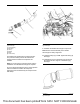
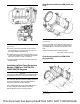
Illustration 16 g03408274
Typical example
5. Connect coolant hose assembly (2) and coolant
hose assembly (3) to the relevant connections on
the engine. Refer to illustration 16.
6. Position clips (4) to coolant hose assembly (2) and
coolant hose assembly (3). Install bolts (5). Tighten
bolts (5) to a torque of 12 N·m (106 lb in).
7. Install the exhaust system to the Clean Emissions
Module (CEM).
Installation of the Clean Emissions
Module (CEM) for 1204F-E44TA,
1204F-E44TTA Engines
NOTICE
Care must be taken when the Clean Emissions Mod-
ule (CEM) is removed from the transportation crate.
After the Clean Emissions Module (CEM) is removed
from the transportation crate, the CEM should be
inspected. Inspect the CEM for damage.
Use a suitable lifting device to lift the CEM. Refer to
“Product Lifting for 1204F-E44TA, and 1204F-
E44TTA Engines” for the correct procedure.
Clean Emissions Module (CEM) (DOC and
SCR)
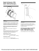
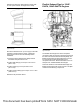
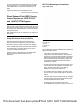
Illustration 17 g03707600
Typical example
To mount the CEM on the application there are four
mounting points (1), two on each mounting bracket.
Use suitable M10 x 1.75 weld nuts with 8.8 or 10.9
bolts.
Tighten the fasteners to the following torque.
. . . . . . . . . . . . . . . . . . . . .100 ± 20 N·m ((74 ± 15 lb ft))
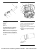
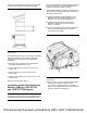
Clean Emissions Module (CEM) (DOC,
DPF, and SCR)
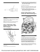
Illustration 18 g03728996
Typical example
This document has been printed from SPI2. NOT FOR RESALE