
User Manual

8
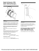
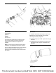
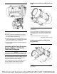
Illustration 13 shows the clamp aligned correctly with
an even space between the edges of the clamp.
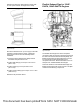
Illustration 14 g03181476
Typical example
Ensure that at least 40 mm (1.57 inch) (A) of the tube
assembly is inserted into the clamp. A temporary
mark can be made on the tube assembly before
installation.
1. Check the spaces between the clamps and the
associated components are even.
2. Tighten ball clamp (2) to a torque of 35 ± 2 N·m
(26 ± 1 lb ft).
3. Tighten clamp (3) to a torque of 55 ± 8 N·m
(41 ± 6 lb ft).
4. Tighten V-band clamp (6) to a torque of 12 ± 1 N·m
(106 ± 9 lb in).
5. Remove the protective sleeve.
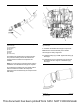
Installation of the Clean Emissions
Module (CEM) for 1206F-E70TA,
and 1206F-E70TTA Engines
NOTICE
Care must be taken when the Clean Emissions Mod-
ule (CEM) is removed from the transportation crate.
After the Clean Emissions Module (CEM) is removed
from the transportation crate, the CEM should be
inspected. Inspect the CEM for damage.
Use a suitable lifting device to lift the CEM. Refer to
“Clean Emission Module (CEM) Only” for the correct
procedure to lift the CEM.
1. Install the CEM to the support bracket on the
application. Ensure that the CEM and support
bracket are correctly seated and aligned.
2. Install the bolts that secure the CEM to the
application. Tighten the bolts to a torque of
190 N·m (140 lb ft).
3. Remove the caps from the electrical components.
Connect harness assembly to the electrical
connections on the CEM.
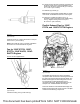
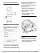
Illustration 15 g03430868
Typical example
4. Remove cap (1). Connect diesel exhaust fluid line
to DEF injector. Remove caps from fluid
connections on the DEF injector. If necessary,
remove caps or plugs from coolant hose assembly
(2) and coolant hose assembly (3).
This document has been printed from SPI2. NOT FOR RESALE