
User Manual

7
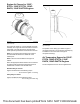
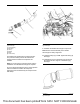
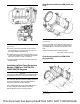
Illustration 11 g03393969
Typical example
(1) Tube assembly
(2) Ball clamp
(3) Clamp
(4) Bellows
(5) Elbow
(6) V-band clamp
The bellows are supplied with a protective sleeve.
The protective sleeve protects the bellows from
damage when the bellows is transported and
installed.
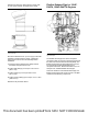
Note: Do not remove the protective sleeve until the
installation of the flexible exhaust pipe is complete.
Do not disturb the bellows from the neutral position
when the bellows is installed. All component
tolerances must be absorbed by the clamps and the
ball clamps.
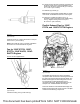
Illustration 12 g03693801
Typical example
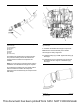
1. Assemble the flexible exhaust pipe components.
Note: Ensure that the assembly of the flexible
exhaust pipe is always supported.
2. Install ball clamp (2) to CEM. Tighten ball clamp (2)
hand tight.
3. Install elbow (5) and V-band clamp (6) to exhaust
back pressure valve. Tighten V-band clamp (6)
hand tight.
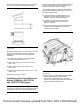
Illustration 13 g03181456
Typical example
This document has been printed from SPI2. NOT FOR RESALE