
User Manual

6
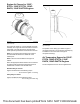
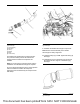
Illustration 8 shows the clamp aligned correctly with
an even space between the edges of the clamp.
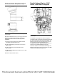
Illustration 9 g03181476
Typical example
Ensure that at least 40 mm (1.57 inch) (A) of the tube
assembly is inserted into the clamp. A temporary
mark can be made on the tube assembly before
installation.
1. Check the spaces between the clamps and the
associated components are even.
2. Tighten ball clamp (2) to a torque of 35 ± 2 N·m
(26 ± 1 lb ft).
3. Tighten clamp (3) to a torque of 55 ± 8 N·m
(41 ± 6 lb ft).
4. Tighten V-band clamp (6) to a torque of 12 ± 1 N·m
(106 ± 9 lb in).
5. Remove the protective sleeve.
Flexible Exhaust Pipe for 1204F-
E44TA, 1204F-E44TTA Engines
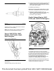
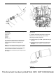
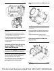
Illustration 10 g03693796
Typical example
The flexible exhaust pipe is a series of separate
components that connect the turbocharger exhaust to
the inlet of the Clean Emissions Module (CEM). The
flexible exhaust pipe has been designed to account
for some lateral or axial misalignment due to
component tolerances. Refer to illustration 10 for an
example of an installed flexible exhaust pipe.
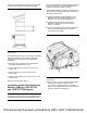
There are variations of the flexible exhaust pipe. All
flexible exhaust pipes will consist of some or multiple
numbers of the following components.
This document has been printed from SPI2. NOT FOR RESALE