
User Manual


53
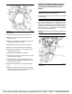
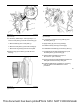
Illustration 107 g03350448
Typical example
1. If necessary, follow Step 1.a through Step 1.c to
remove cover plate (1) from the front housing (5).
a. Remove bolts (2) from cover plate (1).
b. Remove cover plate (1) from front housing (5).
c. Remove O-ring seal (3) from the cover plate.
2. Remove plug (4) in Position (Y) from the front
housing.
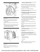
Illustration 108 g03350457
Typical example
Illustration 109 g03350460
Typical example
3. If necessary, install new O-ring seals (6) onto
accessory drive (7).
4. Apply Tooling (A) onto O-ring seals (6).
5. Install accessory drive (7) to housing (5).
6. Install Allen head bolts (8) to accessory drive (7).
7. Equally tighten the Allen head bolts (8) to pull
accessory drive (7) into housing (5).
8. Tighten Allen head bolts to a torque of
25 ± 2.5 N·m (221 ± 22 lb in).
9. Ensure that there is tactile backlash between the
idler gear and the accessory drive gear.
10. Install the OEM driven equipment to accessory
drive (7). Refer to the OEM for the correct
procedure.
■
This document has been printed from SPI2. NOT FOR RESALE