
User Manual


50
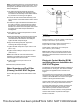
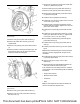
Illustration 102 g02728556
Typical example
2. Use tooling (A) to lubricate the thread of
temperature sensor (2).
3. Install temperature sensor (2) to DPF (3). Tighten
temperature sensor to a torque of 45 ± 5 N·m
(33 ± 4 lb ft)
Note: Ensure correct positioning of the temperature
sensor.
4. Connect harness assembly (1).
5. If necessary, repeat Step 2 through Step 4 to install
the remaining temperature sensor to the DPF.
Differential Pressure Sensor for
854F-E34T Engines
Note: The pipe length or hose length from pressure
point on DPF to sensor must rise continuously to
avoid condensation ingress into the sensor.
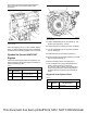
Illustration 103 g03237917
Typical example
Note: The sensor pipe ports should point downwards.
The sensor must not exceed plus or minus 15
degrees from the horizontal.
The vertical pressure port (A) is connected to DPF
inlet side (identified by the larger diameter
connection).
The pressure port (B) is connected to DPF outlet side.
Painting of the 854F-E34T Engine
Painting of the Main Engine Components
Customers are permitted to paint the engine as
received or as part of a power train sub assembly.
These engines are supplied in gray primer.
The customer must not paint the Diesel Particulate
Filter (DPF), Electronic Control Module (ECM),
starting motor, alternator, belts, or the glow plug
control unit.
The customer must use suitable plugs and masks to
an equivalent standard to the engine assembly plant.
The customer must prevent water ingress into the
engine by maintaining an equivalent plugging
standard to the engine assembly plant.
Electrostatic Painting of the Engine
The Electronic Control Module (ECM), sensors and
other electronic components are not proven to be
compatible with electrostatic painting. Perkins does
not recommend use of electrostatic painting on the
engine or ECM.
This document has been printed from SPI2. NOT FOR RESALE