
User Manual


47
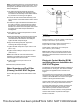
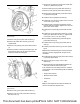
Illustration 96 g03238159
Typical example
1. Remove nuts (3) from power take-off drive (5).
2. Remove cover (1) from power take-off drive (4).
Discard cover (1).
3. Remove O-ring seal (not shown) from power take-
off drive (4). Discard O-ring seal.
4. Remove bolts (7) from power take-off drive (4).
5. Remove cover (6) from power take-off drive (4).
6. Remove O-ring seal (5) from power take-off drive
(4). Discard O-ring seal.
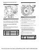
7. Install the driven equipment to studs (2).
8. Install nuts (3) to studs (2). Tighten nuts to a torque
of 45 ± 3 N·m (33 ± 2 lb ft).
9. Install the gear to the driven equipment. Ensure
that the gears are engaged. Tighten the nut for the
gear to the correct torque.
10. Install new O-ring seal (5) to power take-off drive
(4).
11. Install cover (6) to power take-off drive (4). Install
bolts (7) to power take-off drive (4). Tighten bolts to
a torque of 10 ± 1 N·m (89 ± 9 lb in)
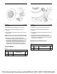
Installation of Driven Equipment to the
Power Take-Off Drive With the Removal
of the Power Take-Off Drive from the
Engine
NOTICE
Keep all parts clean from contaminants.
Contaminants may cause rapid wear and shortened
component life.
NOTICE
Care must be taken to ensure that fluids are con-
tained during performance of inspection, mainte-
nance, testing, adjusting and repair of the product. Be
prepared to collect the fluid with suitable containers
before opening any compartment or disassembling
any component containing fluids.
Dispose of all fluids according to local regulations and
mandates.
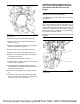
Illustration 97 g02901518
Typical example
This document has been printed from SPI2. NOT FOR RESALE