
User Manual


45
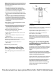
2. Position electric starting motor (3) onto flywheel
housing (1).
Note: Ensure that the electric starting motor is seated
correctly in the starter motor pocket.
3. Install bolts (2) to electric starting motor (3).
Tighten the bolts to a torque of 45 ± 4.5 N·m
(33 ± 3 lb ft)
4. Connect the harness assembly to the electric
starting motor and the solenoid.
Installation of Alternator and Fan
Belts on 854F-E34T Engines
In certain instances, the customer may need to install
the alternator and fan belts to the engine.
If the customer is receiving engines with different fan
pulley diameters and is installing belts of different
lengths, the customer must be able to demonstrate
that a belt of correct length is being assembled to an
individual engine.
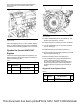
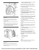
Illustration 92 g02553437
Typical example
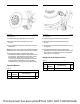
Illustration 93 g02553697
Typical example
1. Ensure that the pulleys and guide rollers are free
from dirt debris, and paint.
2. Install new alternator belt (6) onto pulleys. Ensure
that the alternator belt is centered on all pulleys.
Note: The ribs on the alternator belt must be located
into the grooves of all pulleys.
3. Tighten bolt (1) until adjusting bracket (5) has
reached the full extent of the available adjustment
in Position (A).
4. Tighten bolt (3) to a torque of 50 ± 5 N·m
(37 ± 4 lb ft).
5. Tighten nut and bolt (4) to a torque of 50 ± 5 N·m
(37 ± 4 lb ft)
6. Rotate tensioning bolt (1) two complete revolutions
in a counterclockwise direction. Tighten locking nut
(2) to a torque of 30 ± 3 N·m (266 ± 27 lb in).
This document has been printed from SPI2. NOT FOR RESALE