
User Manual


42
The harness should be supported with brackets to
prevent the mass of the harness straining the
connectors.
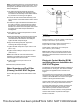
Illustration 85 g03240140
Typical example
Use of the clipping point (1), or other suitable clipping
points, for harness paths should prevent undesirable
movement and loads being applied to the connectors.
Flywheel for Certain 854F-E34T
Engines
Customers that supply flywheels are required to use
bolts sourced from the engine supplier and follow the
defined assembly process.
Table 9
Required Tools
Tool Part Number
Part Description Qty
A
-
Guide Stud
M12 x 1.25 by 100mm
2
B
-
Angle Gauge
1
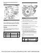
Illustration 86 g02659160
Typical example
1. Install a suitable lifting device to flywheel (1). The
flywheel can weigh 55 kg (121 lb).
2. Install Tooling (A) in Position (X) on the crankshaft.
3. Use the suitable lifting device to position flywheel
(1) onto Tooling (A).
4. Install new bolts (2) hand tight to flywheel (1).
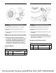
5. Remove Tooling (A) and install remaining new bolts
(2) hand tight to flywheel (1).
6. Remove the lifting device from flywheel (1).
7. Use a suitable tool to prevent the flywheel from
rotating. Tighten bolts (2) to a torque of
30 ± 1.5 N·m (266 ± 13 lb in). Use Tooling (B) to
rotate bolts (2) through an extra 90 degrees in a
clockwise direction to achieve the required final
torque.
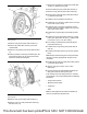
Alignment of the Flywheel Face
Table 10
Required Tools
Tool
Part
Number
Part Description Qty
A
-
Dial Indicator 1
This document has been printed from SPI2. NOT FOR RESALE