
User Manual


41
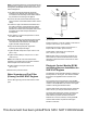
Note: The protective sleeve is not required where the
aftertreatment is rigidly mounted to the engine. In this
arrangement, the bellows will be used to account for
static misalignment.
1. The lower exhaust tube assembly should be
inserted into the bellows tube assembly (loose).
The exhaust tube assembly should slide in without
any excessive force having to be applied.
2. Connect the lower exhaust tube assembly to the
inlet connection of the aftertreatment with a V-band
clamp.
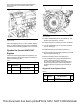
3. Position the upper tube between the bellows and
the outlet connection of the turbocharger. Adjust
the slip joint to ensure that there is good contact
between the surfaces of the ball joints. Ensure that
the ball joints are within the specified limit for
misalignment.
4. Verify that the cup of the ball joint does not touch
the radius of the ball.
5. Slide the ball clamp over the ball joint. Ensure that
the edges of the ball clamp are equidistant and
centered between the radiuses of the ball joint.
Tighten the ball clamp hand tight.
6. Align the remaining ball joints. Tighten the
remaining ball clamps hand tight.
7. Tighten the ball clamps to a torque of 35 ± 2 N·m
(26 ± 1 lb ft).
8. Tighten V-band clamp to a torque of 12 ± 1 N·m
(106 ± 9 lb in).
Note: Ensure that the end of the exhaust tube
assembly is not visible in the slot and the minimum
insertion depth mark cannot be seen.
9. Tighten clamp to a torque of 55 ± 8 N·m
(41 ± 6 lb ft).
10. Remove the protective sleeve.
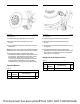
Water Separator and Fuel Filter
(Primary) for 854F-E34T Engines
The fuel filter (primary) has two inlet and two outlet
ports.
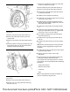
Illustration 84 g03228039
Typical example
Install connections (1) and (2). Tighten connections to
a torque of 20 ± 2 N·m (177 ± 18 lb in).
Install plugs (3) and (4). Tighten connections to a
torque of 22.5 ± 3.5 N·m (199 ± 31 lb in).
Tighten water in fuel sensor (5) to a torque of
2.5 ± 0.25 N·m (22 ± 2.2 lb in).
Note: Tighten water in fuel sensor until the O-ring
seal comes into contact with the bowl of the water
separator. Tighten the water in fuel sensor an extra
180 degrees.
Electronic Control Module (ECM)
and Wiring Harness Installation on
854F-E34T Engines
The Electronic Control Module (ECM) is supplied in a
transit position on the engine. The customer installs
the ECM on the application that is remote to the
engine.
The customer must ensure that the correct ECM is
matched to the correct engine. Ensure that the engine
number on the ECM label is the same as the engine
number on the engine emissions label.
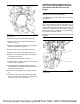
Harness strain relief components must be positioned
within 115 mm (4.5 inch) of each ECM connector.
The strain relief component must be mounted to the
same surface as the ECM. The purpose of each
strain relief is to prevent excessive movement
between the connector, harness, and engine ECM.
Harness strain relief is required for both engine
interface connectors.
This document has been printed from SPI2. NOT FOR RESALE