
User Manual

4
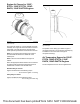
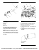
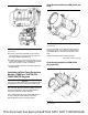
Illustration 3 g03178776
Typical example
Install the sensor (1). Tighten the sensor to a torque
of 20 ± 3 N·m (177 ± 27 lb in).
Note: Ensure that the O-ring is correctly installed to
the sensor. Do not lubricate the O-ring seal.
Fan for 1206F-E70TA, 1206F-
E70TTA, 1204F-E44TA, 1204F-
E44TTA Engines
The fan can be supplied loose.
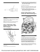
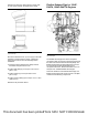
Illustration 4 g03178780
Typical example
1. Remove locking nuts (1) from studs (3).
2. If studs (3) have not been previously removed from
fan drive. Check for the correct installation of the
studs to the fan drive. Tighten studs (3) to a torque
of 11 ± 3 N·m (97 ± 27 lb in).
3. Install fan (2) to studs (3).
Note: Ensure that the label “Radiator Side” is visible
once the fan is installed from the front of the engine.
4. Inspect the condition of locking nuts (1). If
necessary, replace the locking nuts. Install locking
nuts (1). Tighten locking nuts to a torque of
22 ± 5.5 N·m (195 ± 49 lb in).
Flexible Exhaust Pipe for 1206F-
E70TA, and 1206F-E70TTA Engines
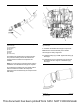
Illustration 5 g03393961
Typical example
The flexible exhaust pipe is a series of separate
components that connect the turbocharger exhaust to
the inlet of the Clean Emissions Module (CEM). The
flexible exhaust pipe has been designed to account
for some lateral or axial misalignment due to
component tolerances. Refer to illustration 5 for an
example of an installed flexible exhaust pipe.
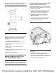
There are variations of the flexible exhaust pipe. All
flexible exhaust pipes will consist of some or multiple
numbers of the following components.
This document has been printed from SPI2. NOT FOR RESALE