
User Manual


39
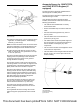
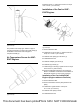
Illustration 79 g03415816
Typical example
The position of the clamp (2) in relation to pipe or
component bead (3) is crucial. Ensure that clamp (2)
is installed on the correct side of the pipe or
component beads (3).
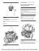
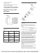
Air Temperature Sensor for 854F-
E34T Engines
Illustration 80 g03227717
Typical example
Install the sensor (1). Tighten the sensor to a torque
of 20 ± 3 N·m (177 ± 27 lb in).
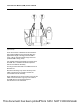
Installation of the Fan for 854F-
E34T Engines
Illustration 81 g03242856
Typical example
1. Remove alternator belt.
2. Install studs (3) to fan drive (1). Tighten studs to a
torque of 11 ± 3 N·m (97 ± 27 lb in)
3. Install fan drive pulley (2) to fan drive (1).
4. Install alternator belt.
5. Install fan adapter (4) to studs (3).
6. Install fan (5) to studs (3).
7. Install nuts (6) to studs (3). Tighten nuts to a torque
of 22 ± 5.5 N·m (195 ± 49 lb in)
8. Ensure that alternator belt is the correct tension.
Refer to “Installation of Alternator and Fan Belts on
854F-E34T Engines” for the correct procedure.
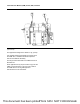
Installation of the Fan for 854F-E34T
Engines (Engines without a Fan Drive)
1. Remove alternator belt.
2. Remove the bolts for the fan pulley. Remove fan
pulley.
3. Install studs. Tighten studs to a torque of
11 ± 3 N·m (97 ± 27 lb in)
4. Install fan drive pulley to studs.
5. Install alternator belt.
This document has been printed from SPI2. NOT FOR RESALE