
User Manual


31
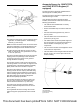
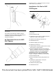
Illustration 65 g03691492
Typical example
4. Position the NOx sensor control modules (5) to the
application in suitable positions. Install bolts (4),
washers (7), and nuts (6).
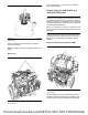
Note: Two bolts should be used to secure the sensor
units to the application. The preferred fastener is an
M6 bolt with a flanged head to distribute the load.
5. Tighten the 8.8 grade bolts to a torque of 9 N·m
(80 lb in). Tighten the 10.9 grade bolts to a torque
of 12 N·m (106 lb in).
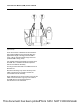
Ensure the harness between the sensor and the first
clipping point is not pulled tight. There should be
enough slack to prevent strain on the grommet
through vibrations and pulling.
The harness must be routed such that the harness
exits the grommet at no more than 15 degrees to the
longitudinal axis of the Sensing Element Assembly
(SEA). Strain relief of the harness is required.
Ensure that the cables to the sensor body and the
sensing unit are not bent. Clip any detached wiring
harness components with cable ties to prevent the
harness chafing against other components. Ensure
that cable straps meet the Original Equipment
Manufactures (OEM) specification.
The harness should be secured every 152.4 mm
(6 inch) or less of length. The bend radius of the
harness should exceed 20 mm (0.7874 inch).
The sensor body must be mounted so that the
maximum ambient temperature does not exceed
85° C (185° F).
The longitudinal axis of the sensing unit must be
within 10 degrees of perpendicular to the exhaust
flow.
Ammonia Sensor for 1204F-E70TA,
and 1204F-E70TTA Engines (If
equipped)
The ammonia sensor should be installed into the
exhaust pipe at a suitable position.
The ammonia sensor module is supplied with a pre-
determined length of cable.
Once the ammonia sensor module has been
installed, ensure that the cables are routed to the
following specifications.
• The cable must be installed with a correctly
secured strain relief.
• Ensure that suitable clips are used to retain the
cable.
• Harness should be supported every 152 mm
(6 inch) or less.
• The bend radius does not exceed 20 mm
(0.7874 inch) at any point.
• The cables should avoid sharp metal edges and
are not restricted. Do not expose the harness to
risks of abrasion or damage by any other
components.
• The route of the harness must mitigate the risk of
contact with hot components.
• The bend radius of the tubing should be more than
50 mm (2 inch). Do not use clips or ties on the
section of tubing.
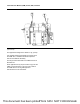
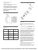
Illustration 66 g03694437
Typical example
(2) Harness assembly
(3) Connector
This document has been printed from SPI2. NOT FOR RESALE