
User Manual


29
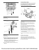
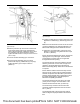
Illustration 62 g03393964
Typical example
2. Remove protective cap from sensor. Ensure that
the threads of NOx sensor have sufficient anti-
sieze compound applied. Install NOx sensor (3) to
the assembly of the clean emissions module.
Tighten the NOx sensor to a torque of 50 ± 10 N·m
(37 ± 7 lb ft).
3. Connect harness assembly (6) to connection.
4. Secure harness assembly (6) in the correct
position with clips (5). Install bolts (4) to clips (5).
Tighten the bolts (4) to a torque of 28 N·m
(248 lb in).
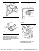
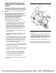
Illustration 63 g03393970
Typical example
5. Position the NOx sensor control module (10) to the
application. Install bolts (7), washers (8), and nuts
(9).
Note: Two bolts should be used to secure the sensor
unit to the application. The preferred fastener is an
M6 bolt with a flanged head to distribute the load.
6. Tighten the 8.8 grade bolts to a torque of 9 N·m
(80 lb in). Tighten the 10.9 grade bolts to a torque
of 12 N·m (106 lb in).
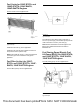
Ensure the harness between the sensor and the first
clipping point is not pulled tight. There should be
enough slack to prevent strain on the grommet
through vibrations and pulling.
The harness must be routed such that the harness
exits the grommet at no more than an angle of 15
degrees to the longitudinal axis of the Sensing
Element Assembly (SEA). Strain relief of the harness
is required.
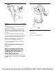
Ensure that the cables to the sensor body and the
sensing unit are not bent. Clip any detached wiring
harness components with cable ties to prevent the
harness chafing against other components. Ensure
that cable straps meet the Original Equipment
Manufactures (OEM) specification.
The harness should be secured every 152.4 mm
(6 inch) or less of length. The bend radius of the
harness should exceed 20 mm (0.7874 inch).
The sensor body must be mounted so that the
maximum ambient temperature does not exceed
85° C (185° F).
The longitudinal axis of the sensing unit must be
within 10 degrees of perpendicular to the exhaust
flow.
This document has been printed from SPI2. NOT FOR RESALE