
User Manual


27
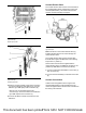
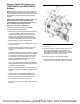
9. Follow Step 4 through Step 6 to install the second
hose assembly. Ensure that hose assembly (14) is
installed in the correct orientation. Refer to
illustration 59.
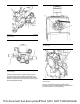
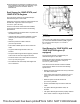
Soot Sensor for 1206F-E70TA, and
1206F-E70TTA Engines
The soot sensor module (2) is supplied with pre-
determined lengths of coax cable.
Fasten the soot sensor module (2) using washers and
two M6 bolts. Tighten the bolts to a torque of
12 ± 3 N·m (106 ± 27 lb in).
Once the soot sensor module has been installed,
ensure that the cables are routed to the following
specifications.
• Rubber grommets should be used in any holes that
the cable is routed into.
• Holes should have a minimum diameter of 16 mm
(0.63 inch) for the antenna connectors to pass
through.
• Retention points are at 200 to 450 mm
(8 to 18 inch) intervals
• Ensure that suitable clips are used to retain the
cable.
• Any spare cable length shall be coiled, not
bundled.
• The spare cable length should be properly retained
at the center of mass to a single fix structure.
• The bend radius or the coil should be no less than
51 mm (2 inch) at any point
• The cables should avoid sharp metal edges and
are not restricted.
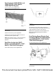
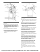
Illustration 60 g03393606
Typical example
Connect the coax cables to the antenna connections
(1) on the Clean Emissions Module (CEM). Tighten
the connections to a torque of 1.2 ± 0.2 N·m
(11 ± 1.8 lb in).
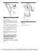
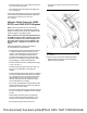
Soot Sensor for 1204F-E44TA, and
1204F-E44TTA Engines (If
equipped)
The soot sensor module is supplied with pre-
determined lengths of coax cable.
Fasten the soot sensor module using washers and
two M6 bolts. Tighten the bolts to a torque of
12 ± 3 N·m (106 ± 27 lb in).
Once the soot sensor module has been installed,
ensure that the cables are routed to the following
specifications.
• Rubber grommets should be used in any holes that
the cable is routed into.
• Holes should have a minimum diameter of 16 mm
(0.63 inch) for the antenna connectors to pass
through.
• Retention points are at 200 to 450 mm
(8 to 18 inch) intervals
• Ensure that suitable clips are used to retain the
cable.
• Any spare cable length shall be coiled, not
bundled.
• The spare cable length should be properly retained
at the center of mass to a single fix structure.
This document has been printed from SPI2. NOT FOR RESALE