
User Manual


21
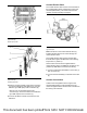
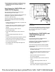
Illustration 42 g06178544
Typical example
(E) DEF pump outlet
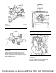
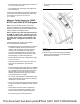
Illustration 43 g06178555
Typical example
(F) DEF injector inlet
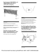
4. Remove cap (8) from DEF pump outlet connection
(E). Remove the plugs from DEF line (9). Connect
DEF line (9) to DEF pump outlet connection (E).
Remove cap (10) from DEF injector inlet
connection (F). Connect the other end of DEF line
(9) to DEF injector inlet connection (F).
5. Connect the DEF line heater connections for the
DEF lines.
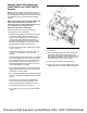
Coolant Diverter Valve
The coolant diverter valve must be on the inlet side of
the manifold (DEF Heater), between the engine and
manifold (DEF Heater). The coolant diverter valve
must be mounted vertically ± 5 degrees.
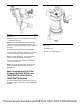
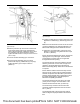
Illustration 44 g03693757
Typical example
Note: The arrow on the coolant diverter valve (3)
indicates the direction flow of coolant through the
coolant diverter valve.
The coolant diverter valve must be mounted with
three M8 bolts. Tighten the M8 bolts of the following
torque 22 N·m (195 lb in).
Quick coolant connectors are supplied with the
coolant diverter valve. The OEM may provide 16 mm
(0.625 inch) SAEJ2044 connectors if necessary.
1. Connect coolant tube assemblies to connection (1)
and connection (4).
2. Connect harness assembly to electrical connection
(2).
Coolant Connections
Coolant must be supplied from the engine to the
manifold (DEF Heater) to heat the DEF tank. The
coolant is supplied via the diverter valve controlled via
the dosing control module.
This document has been printed from SPI2. NOT FOR RESALE