
User Manual


17
DEF Tank Mounting and Installation
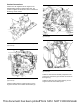
Type 1 DEF Tank
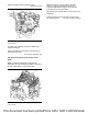
Illustration 34 g03707722
Typical example
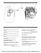
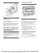
Illustration 35 g03707723
Typical example
Type 1 DEF tanks must be installed to the application
with the following criteria:
• The bottom of the DEF Tank must be fully
supported by a structural platform. Full support is
defined as a continuous material that is at least as
large as the dimensions of the bottom of the tank.
Structural is defined as being able to support full
tank mass with application load without plastic
deformation or failure.
• An anti-friction rubber mat under the bottom of the
tank is required. If the installation uses DEF tank
stops, the anti-friction device must also be
between the stops and the DEF tank.
• Any metallic surfaces contacting the tank should
be free of burrs, welds, foreign objects, and sharp
edges.
• The tank strap must be located correctly. The DEF
tank has strap grooves (1) incorporated into the
DEF tank to help keep the strap in place.
• A minimum clearance of 9 mm (0.35433 inch) (X)
on all sides is required with thick straps in the
grooves.
• The straps should be long enough to support the
dimensions of the fasteners. If there is not enough
free fastener length, assembly may be difficult.
• A locked joint is a requirement and can be
accomplished by using either a jam nut or lock nut.
• The tank straps require a preload when installed.
Thermal expansion and contraction of the tank
may loosen the straps if a preload is not applied.
The preload is a balance between enough preload
to form the strap, to resist slip, to prevent
excessive plastic deformation of the tank and
having adequate life for the components.
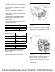
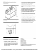
Illustration 36 g03711537
Typical example
(2) Lock nut or weld nut
(3) Jam nut
(A) 45 mm (1.77 inch)
(B) 20 mm (0.79 inch)
(C) 24.25 mm (0.95 inch)
(D) 21.75 mm (0.86 inch)
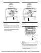
For DEF tanks that have been supplied by the engine
manufacturer, following strap design is
recommended:
This document has been printed from SPI2. NOT FOR RESALE