
User Manual


16
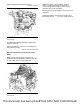
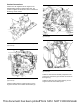
Illustration 32 g03413676
Typical example
(A) Inlet coolant connection
(B) Outlet coolant connection
Coolant is returned from the DEF injector to the inlet
connection on the engine (4).
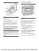
Refer to “Installation of the Clean Emissions Module
(CEM) for 1206F-E70TA, and 1206F-E70TTA
Engines” for an example of the installed coolant
hoses.
Diesel Exhaust Fluid (DEF) Dosing
Control System on 1204F-E44TA,
1204F-E44TTA Engines
NOTICE
DEF system components are supplied with caps and
plug over connection points. Do not remove the caps
and plugs before final assembly to ensure that cleanli-
ness is maintained.
DEF Cleanliness must be adhered to as outlined in
ISO 22241.
Pump Electronics Unit (PEU)
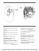
Illustration 33 g03707620
Typical example
After the Pump Electronics Unit (PEU) (1) is removed
from the transportation crate, the PEU should be
inspected. Inspect the PEU for damage.
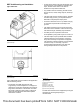
The PEU must be installed to the application with the
following criteria:
• The PEU must be mounted internally or externally
via all four M8 mounting holes (2).
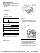
• The mounting face between the four points must
be flat within a tolerance of 0 ± 0.5 mm
(0 ± 0.01968 inch).
• The PEU must be installed vertically ± 5 degrees
with the two DEF connections at the bottom and
the filter at the top. This orientation ensures
injection and purge functionality.
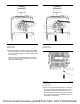
Tighten the M8 fasteners to the following torque.
. . . . . . . . . . . . . . . . . . . . . . 16 ± 1 N·m ((142 ± 9 lb in))
Connect the electrical connection (3) for the PEU.
This document has been printed from SPI2. NOT FOR RESALE