
User Manual


14
Diesel Exhaust Fluid Lines
The diesel exhaust fluid lines must be installed with
the following conditions:
• Be routed as direct as possible with no excessive
dips or sags
• Be routed to avoid abrasion and overheating
• Be adequately supported and not impose stress on
the connector. The maximum clipping details are
detailed in table 1 .
• Must fall within the length guidelines in table 2 .
• Allow for relative movement between the two
components, DEF tank to DEF pump, DEF pump
to DEF injector
• Do not exceed the minimum bend radii. Refer to
table 3 for more information.
Table 1
Maximum clipping distances
Connection to Clip Clip to Clip
Electrical Cable
150 mm (6 inch)
150 to 300 mm
(6 to 12 inch)
150 mm (6 inch)
Table 2
Diesel Exhaust Fluid Lines
Length
Min Max
Suction (DEF tank to pump)
1000 mm
(39.37 inch)
2000 mm
(78.74 inch)
Pressure (pump to DEF injector)
1500 mm
(59.055 inch)
4000 mm
(157.48 inch)
Return (DEF injector to pump)
1500 mm
(59.055 inch)
4500 mm
(177 inch)
Table 3
Diesel exhaust fluid lines
51 mm (2.00787 inch)
Harness
10 mm (0.39370 inch)
Note: For a 12 VDC system, the total length of the
three diesel exhaust fluid lines must not exceed
9500 mm (374 inch).
Note: For a 24 VDC system, the total length of the
three diesel exhaust fluid lines must not exceed
10000 mm (394 inch).
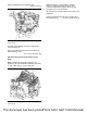
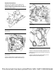
Illustration 26 g03418550
Typical example
1. Remove cap (2) from the connection on the DEF
injector assembly (3). Remove plug from diesel
exhaust fluid line. Connect diesel exhaust fluid line
(1) to DEF injector assembly (3).
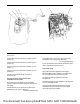
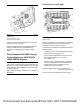
Illustration 27 g03418551
Typical example
2. Remove cap from connector (6) on the PETU (5).
3. Remove plug from diesel exhaust fluid line.
Connect diesel exhaust fluid line (1) to connector
(5).
4. Connect the electrical connection (4) for the diesel
exhaust fluid line.
This document has been printed from SPI2. NOT FOR RESALE