
User Manual


13
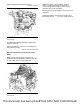
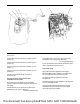
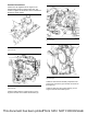
Illustration 25 g03434836
Typical example
Connect diesel exhaust fluid line to position (A) and
position (K).
Connect diesel exhaust fluid line to position (B) and
position (H).
Connect coolant hose assembly to position (C) and
position (L).
Connect coolant hose assembly to position (D) and
position (F).
Connect harness assembly (E) to electrical
connection (G).
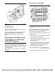
The specifications of the coolant hose
assemblies are as follows.
The total length of the coolant hose assemblies
(supply and return from DEF tank) must be less than
8 m (26 ft).
Internal diameter of connectors and coolant hose
assemblies for the return to DEF tank
. . . . . . . . . . . . . . . . . . . . . . . 15.9 mm ((0.62598 inch))
Internal diameter of connectors and coolant hose
assemblies for the supply of the DEF tank
. . . . . . . . . . . . . . . . . . . . . . . . 9.5 mm ((0.37402 inch))
For the specifications of the diesel exhaust fluid lines,
refer to “Diesel Exhaust Fluid Lines”.
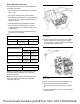
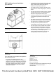
Type 3 DEF Tank
Type 3 DEF tanks are supplied by the Original
Equipment Manufacturer (OEM). Type 3 DEF tanks
are not supplied by the engine manufacturer.
The manifold (DEF) is supplied by the engine
manufacturer.
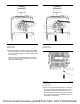
The manifold (DEF) must be installed to the DEF tank
as a sub assembly process.
Contact the applications engineer for the engine
manufacturer if type 3 DEF tank and associated
components are to be installed.
This document has been printed from SPI2. NOT FOR RESALE