
Use And Care Manual


Page 8
SAFETY INSTRUCTIONS
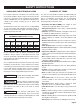
The table below shows the correct size to use, depending
on the cord length and nameplate amperage rating. If
in doubt, use the next heavier gauge. The smaller the gauge
number, the heavier the cord.
Use a proper extension cord. Make sure extension cords
are in good condition. When using an extension cord, be
sure to use a cord that is heavy enough to carry the drawn
current needed by the saw. An undersized cord will cause
a drop in line voltage, resulting in loss of power and
overheating.
GUIDELINES FOR EXTENSION CORDS
Be sure extension cords are properly wired and in good
condition. Always replace a damaged extension cord
or have it repaired by a qualied technician before using it.
Protect extension cords from sharp objects, excessive heat,
and damp or wet areas.
WARNING: Keep the extension cord clear of the
working area. Positon the cord so that it will not get caught
on lumber, tools, or other obstructions while you are working
with a power tool. Failure to do so can result in serious
personal injury.
WARNING: Check extension cords before each
use. If damaged replace immediately. Never use tool with
a damaged cord since touching the damaged area could
cause electrical shock resulting in serious injury.
WARNING: To avoid electrical hazards, re hazards,
or damage to the tool, use proper circuit protection.
Use a separate electrical circuit for power tools. This circuit
should be protected with a time delayed fuse. Before
connecting the tool to the power line, make sure the switch
is in the OFF position and the electric current is rated the
same as the current stamped on the motor’s nameplate.
Running at a lower voltage will damage the motor.
MINIMUM GAUGE (AWG)
EXTENSION CORDS (120V use only)
Amperage rating
Total length
Not Recommended
Not more
than
25'
(7.5 m)
6 18
50'
(15 m)
16
100'
(30 m)
16
150'
(45 m)
14
More
than
0
10 18 16 14 126
12 16 16 14 1210
16 14 1212
The safe use of this product requires an understanding of
the information on the tool and in this operator’s manual as
well as a knowledge of the project you are attempting.
Before use of this product, familiarize yourself with all
operating features and safety rules.
GLOSSARY OF TERMS
• Revolutions Per Minute (RPM): The number of turns
complete by a spinning object in one minute.
• Pulley Housing Cover: Covers pulleys and belt during
operation of drill press.
• Pilot Hole: A small hole drilled in a workpiece that serves
as a guide for drilling large holes accurately.
• Belt Tension Lock Knobs: Tightening knobs lock motor
bracket support to maintain correct belt distance and
tension.
• Head Lock Set Screws: Locks the head to the column.
ALWAYS have them locked in place while operating the
drill press.
• Table Support: Rides on column to support table.
• Column Support: Supports column and provides mounting
holes for column to base.
• Support Lock Handle: Tightening locks table support to
column. Always have it locked in place while operating the
Drill Press.
• Base: Supports Drill Press. For additional stability, holes
are provided in base to bolt Drill Press to bench. (See
“SPECIFIC SAFETY RULES”).
• Feed Return Spring and Cover: Provides means to adjust
quill spring tension.
• Depth Scale: Shows depth of the hole being drilled in
inches.
• Column: Connects head, table, and base on a one-piece
tube for easy alignment and movement.
• Rack: Combines with gear mechanism to provide easy
elevation of the table by the hand operated table bevel
lock.
• Rack Collar: Holds the rack to the column. The rack
remains movable in the collar to permit table support
movements.
• Bevel Scale: Shows degree table is tilted for bevel
operations. Scale is mounted on table support.
• Table Bevel Lock: Locks the table in any position from
0°-45°.
• Table: Provides working surface to support workpiece.
The table of your drill press rotates 360˚ and bevels up to
45˚ for angle drilling.
• Chuck: Clamping devise connected to the spindle to hold
the drill bit or cutting tool.
• Chuck Key: Key used to loosen and tighten the chuck.