
Use And Care Manual


CAUTION: Do not overtighten the two nuts. If the
nuts are tightened too much, the movement of the spindle
and feed handles will be sluggish.
Page 19
ADJUSTMENTS
D
C
C
B
A
A
B
D
A
C
E
E
B
FIG. 14
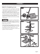
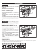
TO SQUARE THE TABLE TO THE HEAD
(Fig. 14)
• Insert a 3 in. (7.6 cm) drill bit (A) into the chuck (B) and
tighten.
• Raise and lock the table (C) about 1 in. (2.5 cm) from the
end of the drill bit.
• Place a combination square (D) on the table as shown.
The drill bit should be parallel to the straight edge of the
square.
• If an adjustment is needed, loosen the table bevel lock (E)
with a adjustment wrench.
• Square the table to the bit by tilting the table.
• Tighten the table bevel lock (E) when square.
FIG. 15
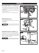
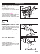
DRILLING DEPTH (Fig. 15)
• To stop the drill at a specic depth for consistent and
repetitive drilling, loosen the depth tension knob (A) located
on the depth scale hub (B).
• Turn the hub until the pointer (C) is aligned to the desired
depth on the scale.
• Tighten the depth tension knob (A). The chuck will stop
after traveling downward to the distance selected.
FIG. 16
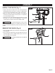
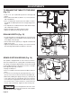
SPINDLE RETURN SPRING (Fig. 16)
The spindle is equipped with an auto-return mechanism.
The main components are a spring and a notched housing.
The spring was properly adjusted at the factory and should
not be readjusted unless absolutely necessary. If it needs
to be adjusted, proceed as follows:
• Unplug the drill press.
• Place a screwdriver into the loop (A) to hold the spring in
place.
• Loosen the two housing nuts (B) approximately 1/4 in.
(6 mm). Do not remove the nuts from the threaded shaft.
• While rmly holding the spring housing (C), carefully pull
it out until it clears the raised notch (D). Turn it until the
next notch (E) is engaged with the raised notch (to increase
the tension, turn it counter-clockwise; to decrease the
tension, turn it clockwise). Tighten the two housing nuts.