
Use And Care Manual


CAUTION: To reduce the risk of injury, keep pulley
housing cover in place and in proper working order when
operating.
Page 18
ADJUSTMENTS
B
B
E
A
A
B
C
D
A
C
E
A
FIG. 11
FIG. 12
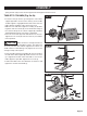
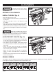
ADJUST SPEEDS AND TENSION THE
BELT (Fig. 11)
• Open the drill press pulley housing cover.
• Loosen the belt tension knobs (A) on both sides of the
drill press head.
• Pull the motor (B) towards the drill press head.
• Set the belt on the desired steps of the motor pulley (C)
and spindle pulley (D) according to the belt positions on
the spindle speed chart on Page. 17.
• Pull the motor away from the drill press head to increase
the belt tension. Tighten the tension knobs (A).
• The belt (E) should be tight enough to prevent slippage.
Correct tension is set if the belt exes about 1/2 in. (13 mm)
when thumb pressure is applied at the midpoint of the
belt between the pulleys.
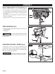
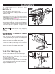
ADJUSTMENTS TO RAISE OR LOWER
TABLE (Fig. 12)
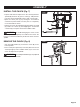
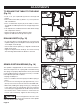
FIG. 13
TO TILT THE TABLE (Fig. 13)
• Raise or lower the table by loosening the column lock
handle (A) and turning the support lock handle (B) until
the table is at the desired height.
• Tighten the column lock handle (A) before drilling.
• Rotate the table around the column by loosening the
column lock handle (A) and turning the table around the
column to the desired position.
• Tighten the column lock handle (A) before drilling.
The table can be tilted from 0-45° to the left and right.
• Loosen the table bevel lock (A) with the adjustment wrench.
• Tilt the table (B) to the desired angle, using the bevel
scale (C) as a basic guide.
• Re-tighten the table bevel lock (A).
• To return the table to its original position, loosen the table
bevel lock. Realign the bevel scale (C) to the 0° setting.
• Tighten the table bevel lock (A).
1/2 in.