
Use And Care Manual


RPM 60Hz∞620
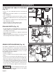
BELT: A-1
E
D
C
B
A
5
4
3
2
1
E
D
C
B
A
5
4
3
2
1
E
D
C
B
A
5
4
3
2
1
E
D
C
B
A
5
4
3
2
1
E
D
C
B
A
5
4
3
2
1
BELT: B-2 BELT: C-3 BELT: D-4 BELT: E-5
RPM 60Hz∞1150 RPM 60Hz∞1630 RPM 60Hz∞2180 RPM 60Hz∞3070
1 2 3 4 5
ADJUSTMENTS
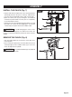
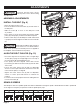
CAUTION: The belt (D) should be tight enough to
prevent slippage. Correct tension is set if the belt exes
about 1/2 in. (13 mm) when thumb pressure is applied at
the midpoint of the belt between the pulleys.
Page 17
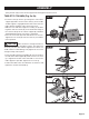
INSTALL THE BELT (Fig. 9)
ASSEMBLY ADJUSTMENTS
• Open the pulley housing cover.
• Loosen the belt tension lock knobs (A) on both sides of
the drill press.
• Slide the motor (B) as close to the drill press head
as possible.
• Place a belt (C) on the motor pulley (D) and the spindle
pulley (E) in the proper position for the desired speed.
• Pull the motor away from the drill press head until the belt
is properly tensioned. Tighten the belt tension lock knobs
(A).
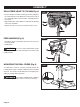
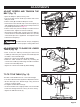
ALIGN THE BELT PULLEYS (Fig. 10)
• Check the alignment of the pulleys with a straight edge
of ruler (A) by laying the straight edge across the top of
the motor pulley (B) and spindle pulley (C).
• If the pulleys are NOT aligned, release belt tension
by loosening the belt tension lock knobs (D) on both sides
of the head.
• Loosen the motor mount nuts (E) with an adjustable
wrench or 13mm open-end wrench, and lower or raise the
motor until the pulleys are aligned.
• Tighten the motor mount nuts (E) with an adjustable
wrench or 13mm open-end wrench to maintain the
position.
• Lock the motor for the proper belt tension and tighten the
tension lock knobs (D).
WARNING: To prevent personal injury, always
disconnect the plug from the power source when making
any adjustment.
B
A
D
E
C
A
FIG. 9
D
B
C
A
D
E
E
FIG. 10
SPINDLE SPEEDS
This drill press offers ve spindle speeds from 620 to 3070 RPM. The highest speed is obtained when the belt is positioned
on the largest motor pulley step and the smallest spindle pulley stop.