
Use And Care Manual

14
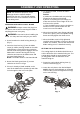
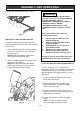
SETTING THE BEVEL CUTTING ANGLE
The sole plate can be set to perform bevel cuts
up to 45°.
1. Rotate the bevel angle locking lever (1)
counter clockwise (Fig. 3).
2. Rotate the sole plate (2) to the desired angle.
NOTES:
a) Align the desired angle on the bevel scale
(3) with the alignment mark (4) on the sole
plate housing.
b) Always make a test cut on a scrap
workpiece and check to make sure the bevel
cut is correct.
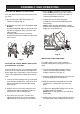
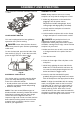
SETTING THE "ZERO" BEVEL ANGLE FOR
ACCURATE 90° CUTTING
Before making any cuts, it is important to make
a test cut on a scrap workpiece and adjust the
bevel angle stop if necessary to ensure that the
"zero" bevel adjustment provides accurate 90°
cuts.
1. Loosen the bevel locking lever (1) and rotate
the sole plate toward the 0° mark as far as it
will go and tighten the bevel angle locking
lever (Fig 4).
2. Make a test cut on a scrap workpiece and
check the cut with a carpenters’ square to
verify that the saw is cutting at 90°.
3. If the test cut is not at 90°, turn the zero
adjustment lock nut (2) counter clockwise
approximately ¼ turn using a 7mm wrench.
4. Use a #2 screwdriver to turn the zero
bevel adjusting screw (3) in or out until the
saw is cutting at 90° when the sole plate is
contacting the adjusting screw.
5. Tighten the lock nut while using the
screwdriver to prevent the adjusting screw
from turning.
NOTE: When the final adjustment is made
and the locknut tightened, recheck the cutting
angle on a scrap workpiece.
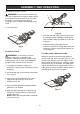
INSTALLING THE EDGE GUIDE
The edge guide can be used to facilitate
accurate cutting when ripping pieces up to 5"
wide.
1. Loosen the edge guide locking screw (1)
counter clockwise approximately 2 turns
using the 5mm hex key (Fig. 5).
2. Slide the edge guide mounting rod (2) into the
mounting slots (3) in the sole plate.
3. Align the desired cutting width on the scale
(4) with the 0° cutting mark (5) in the sole
plate.
4. Tighten the edge guide locking screw to lock
the edge guide into position.
NOTE: Do not over tighten as you may strip
the threads.
5. Make a test cut on a scrap workpiece to verify
the edge guide setting. Adjust as necessary.
ASSEMBLY AND OPERATING
Fig. 3
1
2
3
4
Fig. 4
1
2
3