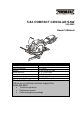
5.8A COMPACT CIRCULAR SAW 241-0943 Owner’s Manual Rating: Motor Amperage: Speed: Blade diameter: Arbor: Depth of cut @ 90°: Depth of cut @ 45°: PRODUCT SPECIFICATIONS 120 V, 60 Hz, AC 5.8 Amps 3,500 RPM (no load) 4 ½" (114.3 mm) 3/8" (9.5 mm) 1-11/16" (42.9 mm) 1-1/8" (28.
TABLE OF CONTENTS Product specifications ………….………………………………………………………………... Table of contents …………………………………………………………………….................. General safety warnings ………………………………………………………………………… Eye, ear & lung protection ………………………………………………………………………. Electrical safety …………………………………………………………………………………... Power tool safety …………………………………………………………………….................. General warning …………………………………………………………………………………. Work area ………………………………………………………………….……………………... Electrical safety …………………………………………………………………………………...
GENERAL SAFETY WARNINGS ! WARNING: Before using this tool or any of its accessories, read this manual and follow all Safety Rules and Operating Instructions. The important precautions, safeguards and instructions appearing in this manual are not meant to cover all possible situations. It must be understood that common sense and caution are factors which cannot be built into the product.
GENERAL SAFETY WARNINGS WEAR A DUST MASK THAT IS DESIGNED TO BE USED WHEN OPERATING A POWER TOOL IN A DUSTY ENVIRONMENT. ! WARNING: Dust that is created by power sanding, sawing, grinding, drilling, and other construction activities may contain chemicals that are known to cause cancer, birth defects, or other genetic abnormalities.
POWER TOOL SAFETY ! WARNING: Read all safety warnings and instructions. Failure to follow the warnings and instructions may result in electric shock, fire and/or serious injury. If operating a power tool in a damp location is unavoidable, use a residual current device (RCD) protected supply. Use of a ground fault circuit interrupter (GFCI) reduces the risk of electric shock. Save all warnings and instructions for future reference.
POWER TOOL SAFETY Power tool use and care Use clamps or another practical way to secure and support the workpiece to a stable platform. Holding the work by hand or against your body leaves it unstable and may lead to loss of control. Do not force the power tool. Use the correct power tool for your application. The correct power tool will do the job better and safer at the rate for which it was designed. Service Do not use the power tool if the switch does not turn it on and off.
SPECIFIC SAFETY RULES ! WARNING: Know your circular saw. Do not plug the tool into the power source until you have read and understand this Instruction Manual. Learn the tool’s applications and limitations, as well as the specific potential hazards related to this tool. Following this rule will reduce the risk of electric shock, fire, or serious injury. Hold power tool by insulated gripping surfaces when performing an operation where the cutting tool may contact hidden wiring or its own cord.
SPECIFIC SAFETY RULES CAUSES AND OPERATOR PREVENTION OF KICKBACK – cont’d Use extra caution when making a "plunge cut" into existing walls or other blind areas. The protruding blade may cut objects that can cause kickback. Maintain a firm grip on the saw and position your arms to resist kickback forces. Position your body to the left or right side of the blade, but not in line with the blade.
SPECIFIC SAFETY RULES ADDITIONAL SPECIFIC SAFETY RULES – cont’d Never use the side of the blade for cutting. When making horizontal cuts, make sure the weight of the tool is not forcing the side of the blade to do the cutting. This will reduce the risk of kickback. Make sure there are no nails or foreign objects in the area of the workpiece to be cut. Never lay workpiece on hard surfaces like concrete, stone, etc. The protruding blade may cause tool to jump.
EXTENSION CORD SAFETY ! WARNING: Keep the extension cord clear of the working area. Position the cord so it will not get caught on the workpiece, tools or any other obstructions while you are working with the power tool. ! WARNING: Repair or replace damaged or worn extension cords immediately. Make sure any extension cord used with this tool is in good condition. When using an extension cord, be sure to use one of heavy enough gauge to carry the current the tool will draw.
SYMBOLS ! WARNING: Some of the following symbols may appear on the circular saw. Study these symbols and learn their meaning. Proper interpretation of these symbols will allow for more efficient and safer operation of this tool. V A Hz W kW L kg H N/cm2 Pa OPM Min S or a.c.
KNOW YOUR CIRCULAR SAW Main handle Adjustable vacuum adapter Motor vents Hex key Laser Bevel adjustment lever Lock-off button ON/OFF Trigger switch Edge guide locking screw Blade guard Blade guard lever 4 ½ x 3/8 24TCT blade Edge guide Shaft locking button Depth adjustment lever 12 Laser ON/OFF switch Bevel adjustment stop
ASSEMBLY AND OPERATING 5. To reinstall a blade, reverse the above procedure. NOTES: a) Make sure the blade teeth are pointing forward at the bottom of the blade. b) When re-installing the outer flange nut make sure the flats of the flange nut fit over the flats on the spindle. c) Turn the blade screw counter clockwise to thread it into the spindle. Make sure the screw is not cross threaded. NOTE: For illustrative purposes, some drawings show the vacuum adaptor installed on the saw.
ASSEMBLY AND OPERATING SETTING THE BEVEL CUTTING ANGLE 4. Use a #2 screwdriver to turn the zero bevel adjusting screw (3) in or out until the saw is cutting at 90° when the sole plate is contacting the adjusting screw. The sole plate can be set to perform bevel cuts up to 45°. 1. Rotate the bevel angle locking lever (1) counter clockwise (Fig. 3). 5. Tighten the lock nut while using the screwdriver to prevent the adjusting screw from turning.
ASSEMBLY AND OPERATING INSTALLING THE EDGE GUIDE – cont’d 3 ! WARNING 1 5 For safety reasons, the operator must read the sections of this Owner’s Manual entitled "GENERAL SAFETY WARNINGS", "POWER TOOL SAFETY", "SPECIFIC SAFETY RULES", "EXTENSION CORD SAFETY" and "SYMBOLS" before using this circular saw. 3 2 4 Verify the following every time the circular saw is used: Fig. 5 INSTALLING THE VACUUM ADAPTER 1.
ASSEMBLY AND OPERATING LOCK-OFF BUTTON AND TRIGGER SWITCH – cont’d GENERAL CUTTING NOTE: Always make a test cut on a scrap workpiece to verify that all settings are correct. 1. Make any adjustments to the saw before plugging it into the power source. Adjustments include cutting depth, bevel cutting angle and edge guide (if installed). 1 2 2. Clearly mark the workpiece to locate the position of the cut. Fig. 7 3. Hold a smaller workpiece with a vise. Clamp a larger workpiece to a work bench or table.
ASSEMBLY AND OPERATING GENERAL CUTTING – cont’d ! WARNING: Do not force the circular saw. Use only enough force to keep the blade cutting at full speed. Excessive pressure on the blade will cause it to slow down and overheat, resulting in poor cut quality and damage to the motor. 1 2 9. Turn laser OFF. 3 Fig. 10 3 6. Start the saw and slowly lower the blade onto the workpiece while holding the blade guard lever forward to allow the blade to cut into the workpiece. 2 1 7.
ASSEMBLY AND OPERATING CHANGING THE LASER BATTERIES The batteries that operate the laser will have to be replaced after considerable use of the laser. 2 1. Turn the laser switch OFF. 2. Remove the laser cover screw (1) using a #2 screwdriver (Fig. 12). 3 1 4 Fig. 13 Fig. 12 3. Lift the laser cover (2) off the top of the laser assembly (Fig. 13). 4. Remove the two old batteries (3). ! DANGER: Never allow the laser beam to shine into a person’s eyes. Serious eye damage could result.
MAINTENANCE GENERAL It has been found that electric tools are subjected to accelerated wear and possible premature failure when they are used on fiberglass boats and sports cars, wallboard, spackling compounds or plaster. The chips and grindings from these materials are highly abrasive to electric tool parts such as bearings, brushes, commutators, etc. Consequently, it is not recommended that this tool be used for extended work on any fiberglass material, wallboard, spackling compounds or plaster.
EXPLODED VIEW 12 13 14 15 37 36 16 17 18 35 34 21 33 20 19 22 32 23 31 30 25 11 24 9 26 29 28 27 6 38 43 3 39 74 40 41 28 44 46 75 71 47 48 5 1 73 72 42 8 2 8 45 4 7 10 76 77 70 78 79 80 49 81 50 82 83 51 69 52 84 85 68 86 53 67 54 66 65 55 64 63 62 61 56 57 58 59 60 20
PARTS LIST ! WARNING: When servicing, use only original equipment replacement parts. The use of any other parts may create a safety hazard or cause damage to the circular saw. Any attempt to repair or replace electrical parts on this circular saw may create a safety hazard unless repairs are performed by a qualified technician. For more information, call the Toll-free Helpline, at 1-866-349-8665 Monday – Friday from 9am to 5pm Eastern Standard Time. Always order by PART NUMBER, not by key number.
PARTS LIST Key # 35 36 37 38 39 40 41 42 43 44 45 46 47 48 49 50 51 52 53 54 55 56 57 58 59 60 61 62 63 64 65 66 67 68 69 70 71 72 73 74 75 76 77 78 79 Part # 3120020163 4020010169 3180040128 4050040016 4010020004 2030020362 2040080058 2040040129 2020020057 2040080059 2010080150 4010010154 2040040130 4030010074 4060010041 2030030300 4100020012 4020010003 4060010005 2030020240 4060010016 4020080019 2050060271 2030010068 2030290004 6140020013 4020010005 3120100061 4130010019 4020010167 3150190207 4020010175
PARTS LIST Key # Part # 80 81 82 83 84 85 86 4020200002 2020080048 4100020028 2010140062 6070100004 2010140063 4050050011 Part Name Screw Lower blade guard Snap ring 22 Inner flange 24TCT blade Outer flange Screw M5*14(L) 23 Quantity 1 1 1 1 1 1 1
PERFORMAX® CIRCULAR SAW WARRANTY 30-DAY MONEY BACK GUARANTEE: This PERFORMAX® brand power tool carries our 30-Day Money Back Guarantee. If you are not completely satisfied with your PERFORMAX® brand power tool for any reason within thirty (30) days from the date of purchase, return the tool with your original receipt to any MENARDS ® retail store, and we will provide you a refund – no questions asked.