
Datasheet
3
Subject to reasonable modifications due to technical advances. Copyright Pepperl+Fuchs, Printed in Germany
Pepperl+Fuchs Group • Tel.: Germany +49 621 776-0 • USA +1 330 4253555 • Singapore +65 67799091 • Internet http://www.pepperl-fuchs.com
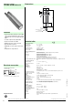
UC2000-30GM-E6R2-V15
Ultrasonic sensor
LED Displays
LED ON indicates closed switch output.
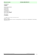
Note on communication with the UC-30GM-R2 interface cable
The UC-30GM-R2 interface cable allows for communication with the ultrasonic sensor using the ULTRA 2001 service program.
The cable creates a connection between the PC-internal RS 232 interface and the plug-in connection for the temperature/pro-
gram plug on the sensor. When setting up the connection on the sensor, make certain the plug is lined up correctly; otherwise
no communication will be possible. The protrusion of the round plug must be inserted into the groove of the plug connection
on the sensor side and
not into the arrow symbol on the sensor.
Adjustable parameter with service program ULTRA 2001
- Switching point 1 and 2
- NO/NC function
- Mode of operation
-Sonic speed
- Temperature offset (The inherent temperature-rise of the sensor can be considered in the temperature compensation)
- Expansion of the unusable area (for suppression of unusable area echoes)
- Reduction of the detection range (for suppression of remote range echoes)
- Time of measuring cycle
- Acoustic power (interference of the burst duration)
- Sensitivity
- Behaviour of the sensor in case of echo loss
- Behaviour of the sensor in case of a fault
- Average formation via an allowed number of measuring cycles
- On/off-delay
- Switching hysteresis
- Selection of the parameter set, RS 232 or manually.
Mounting aids
BF30
BF30F
BF5-30
M-105
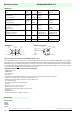
Displays in dependence on operating
mode
Dual LED
green
LED
red
LED
yellow A1
LED
yellow A2
TEACH-IN of switching point A1
object detected
no object detected
flashing
off
off
flashing
flashing
flashing
off
off
TEACH-IN switching point A2
object detected
no object detected
flashing
off
off
flashing
off
off
flashing
flashing
TEACH-IN mode of operation (E2/E3)
two independent switching points
window mode
Hysteresis mode
on
on
on
off
off
off
flashing
off
flashing
off
flashing
flashing
Normal mode
temperature compensated
plug pulled or shorted
on
off
off
on
switching state A1
switching state A1
switching state A2
switching state A2
Interference (e.g. compressed air) off flashing last or defined condi-
tion
last or defined condi-
tion
Standby flashes off previous state previous state
Accessories
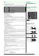
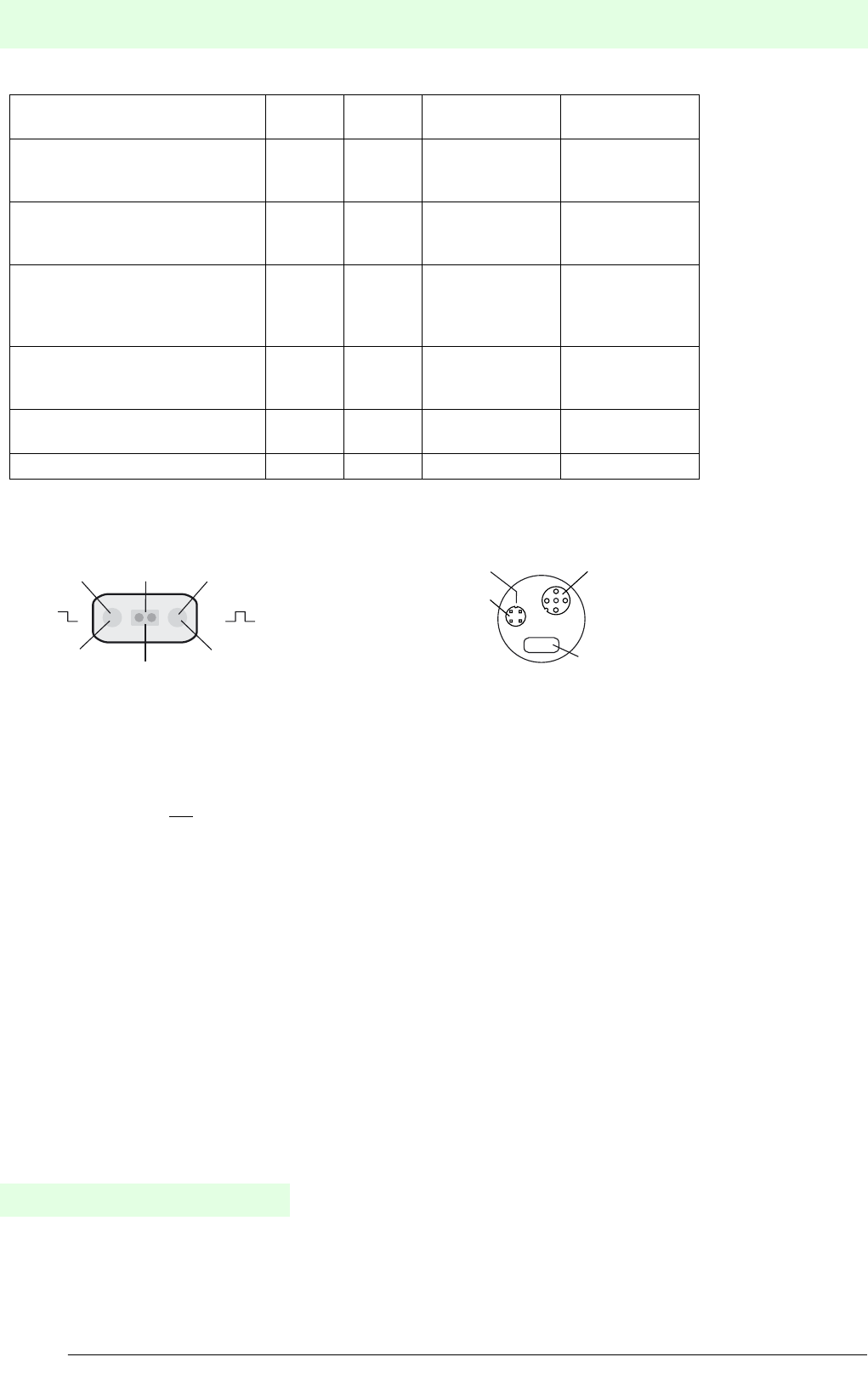
E2 E3
A1 A2
LED
yellow
Dual-LED
green/red
LED
yellow
Switch output 1
"Power on"/Disturbance
Switch output 2
LED-Window
RS 232-connection
LED-window
V15-plug connector
(M12x1)
1: TXD
2: RXD
3: not used
4: GND
Temperature/program
connector
(PC connection via inter-
face cable UC-30GM-R2)
Groove
1
2
4
3