
Datasheet
2
Subject to reasonable modifications due to technical advances. Copyright Pepperl+Fuchs, Printed in Germany
Pepperl+Fuchs Group • Tel.: Germany +49 621 776-0 • USA +1 330 4253555 • Singapore +65 67799091 • Internet http://www.pepperl-fuchs.com
HinweiseNotes BestellbezeichnungModel number
UC2000-30GM-E6R2-V15
Characteristic curves/additional
information
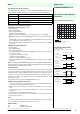
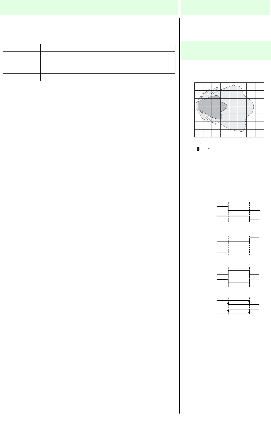
Characteristic response curve
Distance X [m]
Distance Y [m]
Curve 1: flat surface 100 mm x 100 mm
Curve 2: round bar, Ø 25 mm
0.0 0.5 1.0 1.5 2.0 2.5 3.0 3.5 4.0
0.6
0.4
0.2
0.0
-0.2
-0.4
-0.6
-0.8
1
2
X
Y
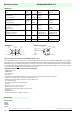
Switch point 1
Switch point 2
A 1 (N.O.)
Switch output 1
A 2 (N.O.)
Switch output 2
A 1 (N.C.)
Switch output 1
A2 (N.C.)
Switch output 2
A 1 (N.O.)
Switch output 1
A2 (N.C.)
Switch output 2
A 1 (N.O.)
Switch output 1
A2 (N.C.)
Switch output 2
1. Switch point mode
When A1 < A2, both switch outputs are activated as
N.O. contacts.
2. Window mode
To exchange the switching distances is of no effect.
3. Hysteresis mode
To exchange the switching distances is of no effect.
When A1 > A2, both switch outputs are activated as
N.C. contacts.
Possible operating modes
Description of the sensor functions
This ultrasonic sensor features a four-pole temperature/TEACH-IN plug, that can
be connected in four different positions. These have the following significance.
Description of the TEACH-IN procedure
TEACH-IN of switching points 1 or 2
- Cut supply voltage
- Remove TEACH-IN plug
- Restore supply voltage (Reset)
- Set object to desired switching point
- Plug and remove the TEACH-IN plug in pos. A1 or A2. Switching point A1 or A2 is taught.
Caution: Removing the temperature/TEACH-IN plug, the values of the object position will be adopt-
ed.
- The TEACH-IN procedure is controlled with the LED. The green LED flashes, when object is detect-
ed, the red LED flashes when no object is detected.
- Connect TEACH-IN plug in pos. T. The TEACH-IN procedure is completed, the sensor is working in
normal mode.
TEACH-IN of switching function
- Cut supply voltage
- Remove TEACH-IN plug
- Restore supply voltage (Reset)
- Connect TEACH-IN plug in pos. E2/E3. By multiple plugging, three different modes of operation can
be set in cyclical sequence:
• switching point mode, LED A1 is flashing,
• window mode, LED A2 is flashing
• hysteresis mode, LED A1 and A2 are flashing
- Connect TEACH-IN plug in pos. T. The TEACH-IN procedure is completed, the sensor is working in
normal mode.
Note: If the temperature/TEACH-IN plug has not been plugged in within 5 minutes
in position T, the sensor will return to normal mode (with the latest permanent stored
values) without temperature compensation.
Synchronisation
The sensor features a synchronisation input for the suppression of mutual interference. If this input is
not used, the sensor will operate using an internally generated clock rate. It can be synchronised by
applying a square wave voltage. A falling edge leads to the transmission of a single ultrasonic pulse.
A low level
≥
1 s or an open synchronisation input will result in the normal operation of the sensor.
A high level > 1 s will result in the standby mode of the sensor (indicator green LED). The outputs
pause in the latest status.
Synchronisation cannot be performed during TEACH-IN and vice versa.
Multiple operating modes are possible
1. Two to five sensors can be synchronised by interconnecting their synchronisation inputs. In this
case, the sensors alternately transmit ultrasonic pulses.
2. Multiple sensors can be controlled by the same synchronisation signal. The sensors are synchro-
nised.
3. The synchronisation pulses are sent cyclically to individual sensors. The sensors operate in mul-
tiplex mode.
4. A high level at the synchronisation input disables the sensor.
The response time increases when the sensor is synchronised, because the synchronisation increas-
es the measurement cycle time.
Note:
If the option for synchronisation is not used, the synchronisation input has to be connected to ground
(0V) or the sensor has to be operated via a V1 cable connector (4-pin).
Default setting
A1: unusable area
A2: nominal sensing range
Plug position Meaning
A1 TEACH-IN switching point A1
A2 TEACH-IN switching point A2
E2/E3 Switching: 2 independent switching points/window mode/hysteresis mode
T Temperature compensation