
Datasheet


Subject to reasonable modifications due to technical advances. Copyright Pepperl+Fuchs, Printed in Germany
Pepperl+Fuchs Group • Tel.: Germany +49 621 776-0 • USA +1 330 4253555 • Singapore +65 67799091 • Internet http://www.pepperl-fuchs.com
Ultrasonic sensor UB4000-F42-E5-V15
2
Release date: 2009-10-22 13:22 Date of issue: 2009-10-22 134000_ENG.xml
Functional Description
The sensor may be completely parameterised via two keys on the side panel of the
housing. As a special feature provided by this sensor, the ultrasound beam width
may be adapted to the environmental conditions at the place of operation of the sen-
sor.
Specifying the switching points:
When specifying the switching points, the user determines at which points the
switching output changes its state. The order of the switching points A1 > A2, or A1
< A2 also determines the direction of action (i.e. normally-closed/normally-open con-
tact function).
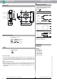
Dimensions
Electrical Connection
Pinout
Membrane keys
LED window
7.5
52.5
15.5
5.2
30
10
5
34
15
M12x1
80
65
80
65
16
34
A
1
A
2
TEACH IN
MODE SET
Standard symbol/Connections:
(version E5, pnp)
Program input
Sync. input
Switch output
Wire colors in accordance with EN 60947-5-2.
+ U
B
1
- U
B
2
4
3
5
(BN)
(WH)
(GY)
(BK)
(BU)
U
Connector V15
2
3
1
4
5
Additional Information
Accessories
MH 04-3505
Mounting aid
MHW 11
Mounting aid
V15-G-2M-PVC
Cable connector
V15-W-2M-PUR
Cable connector
Programmable operation modes
Object distance
1. Switching point mode
N. C.
A2
N. O.
A1
Object-
presence
A1, A2
3. Hysteresis mode
N. C.
A2 > A1
N. O.
A1 > A2
Detection-
limit
2. Window mode
N. O.
A2 > A1
N. C.
A1> A2
Note:
means: cover transducer surface with your hand,
while teaching the switching point.
If A1 = A2, the output works like A2 > A1
Unusable area
A1
A2
A1
A2 A1
A2
A1
A2
A2
A1