
Datasheet
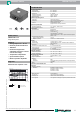

Ultrasonic sensor UB2000-F42-I-V15
4
Release date: 2016-08-01 13:41 Date of issue: 2016-08-01 133990_eng.xml
Germany: +49 621 776 4411Pepperl+Fuchs Group
Refer to “General Notes Relating to Pepperl+Fuchs Product Information”.
USA: +1 330 486 0001 Singapore: +65 6779 9091
www.pepperl-fuchs.com fa-info@us.pepperl-fuchs.com fa-info@sg.pepperl-fuchs.com
fa-info@de.pepperl-fuchs.com
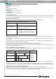
Hold down the A1 key for 2 seconds to save the selected beam shape, terminate the parameterisation and ensure that the sen-
sor returns to normal mode. Briefly press the A1 key to return to Step 1 (parameterisation of the output function).
If the parameterisation mode is not terminated within 5 minutes (hold down the A1 key for 2 seconds), the sensor aborts this
mode without modifying the settings.
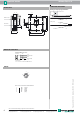
Synchronisation
The sensor provides a synchronisation port to suppress mutual influencing. If this port has not been connected, the sensor
works at an internally generated cycle rate. Several sensors may be synchronised via the following options.
External synchronisation:
The sensor may be synchronised via the external application of a square wave voltage. A synchronisation pulse on the syn-
chronisation input initiates a measuring cycle. The pulse width must be greater than 100 µs. The measuring cycle is started with
the falling edge. A low level > 1 s or an open synchronisation input initiate the transition to normal sensor mode. A high level on
the synchronisation input deactivates the sensor.
Two modes are possible:
- Several sensors are controlled via the same synchronisation signal. The sensors work in common mode.
- The synchronisation pulses are forwarded at cyclic intervals to respectively one single sensor. The sensors work in multiplex mode.
Self-synchronisation:
The synchronisation ports of up to 5 sensors suitable for self-synchronisation are connected to each other. These sensors work
in multiplex mode after Power on. The On delay increases depending on the number of sensors to be synchronised. While the
learn mode is active, no synchronisation is possible (and vice-versa). To specify the switching points, the sensors must be op-
erated in non-synchronised mode.
Note:
If the synchronisation option is not used, the synchronisation input must be connected to ground (0V) or the sensor must be
operated with a (4-pole) V1 connecting cable.
Beam width Flash sequence of the red LED A2 key
Small beam
Medium beam
Large beam
pause
pause
pause