
Datasheet
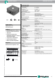

Ultrasonic sensor UB2000-F42-I-V15
3
Release date: 2016-08-01 13:41 Date of issue: 2016-08-01 133990_eng.xml
Germany: +49 621 776 4411Pepperl+Fuchs Group
Refer to “General Notes Relating to Pepperl+Fuchs Product Information”.
USA: +1 330 486 0001 Singapore: +65 6779 9091
www.pepperl-fuchs.com fa-info@us.pepperl-fuchs.com fa-info@sg.pepperl-fuchs.com
fa-info@de.pepperl-fuchs.com
Functional Description
The sensor may be completely parameterised via two keys on the side panel of the housing. As a special feature provided by
this sensor, the ultrasound beam width may be adapted to the environmental conditions at the place of operation of the sensor.
Specifying the evaluation limits:
The evaluation limits determine the characteristic line and the working range of the analog output.
The A2 evaluation limit is specified via the A2 key, analogous to the description above.
Alternatively, the evaluation limits may also be specified electrically via the learn input. To specify the A1 evaluation limit, the
learn input must be connected to
-U
B
; to specify the A2 evaluation limit, it must be connected to +U
B
. Specified values are saved upon the disconnection from
the learn input.
Evaluation limits may only be specified within the first 5 minutes after Power on. To modify the evaluation limits later, the user
may specify the desired values only after a new Power On.
Proceed as follows to parameterise the output function and the ultrasound beam width:
Press the A1 key during Power on and hold down the key for another second to ensure that the sensor starts the two-step pa-
rameterisation of the operating modes.
Step 1, parameterisation of the output function
The output function parameterised last is displayed. All output functions available may be selected via consecutive, brief strokes
of the A2 key. These strokes are visualised via short flashes of the green LED.
The "Zero point straight line“ setting fixedly specifies the A1 evaluation limit to 0 (see specification of the evaluation limits). The
A2 evaluation limit determines the steepness of the output characteristic line.
Hold down the A1 key for 2 seconds to save the selected output mode, complete the parameterisation and ensure that the sen-
sor returns to normal mode. If you briefly press the A1 key, Step 2 is entered (parameterisation of the ultrasound beam width).
Step 2, parameterisation of the ultrasound beam width
Via Step 2, the ultrasound beam width may be adapted to the requirements of the corresponding application.
The beam width parameterised last is displayed first. Available beam width settings may be selected via consecutive, brief
strokes of the A2 key. These strokes are visualised via the flash sequence of the red LED.
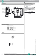
Accessories
MH 04-3505
Mounting aid for FP and F42 sensors
MHW 11
Mounting brackets for sensors
DA5-IU-2K-V
Process control and indication equipment
V15-G-2M-PVC
Female cordset, M12, 5-pin, PVC cable
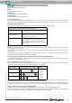
Specifying the A1 evaluation limit by pressing the A1 key
Holding down the A1key > 2
seconds
The sensor switches to learn mode and the user may
specify the A1 evaluation limit
Position the target object at
the desired distance
The yellow LED of the sensor flashes fast to indicate
that the target object is recognised. The red LED flash-
es if the object is not recognised.
Briefly pressing the A1 key The sensor terminates the specification of the A1 eval-
uation limit and saves it as a non-volatile value. The
specified value is invalid if the object is uncertain (i.e.
the red LED lights up at irregular intervals). The learn
mode is exited.
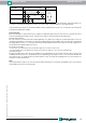
Operating mode Flash sequence of the green LED A2 key
Rising edge
Falling edge
Zero point straight
line
pause
pause
pause