
Datasheet
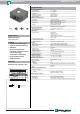

Ultrasonic sensor UB2000-F42-E6-V15
4
Release date: 2016-08-01 13:41 Date of issue: 2016-08-01 133988_eng.xml
Germany: +49 621 776 4411Pepperl+Fuchs Group
Refer to “General Notes Relating to Pepperl+Fuchs Product Information”.
USA: +1 330 486 0001 Singapore: +65 6779 9091
www.pepperl-fuchs.com fa-info@us.pepperl-fuchs.com fa-info@sg.pepperl-fuchs.com
fa-info@de.pepperl-fuchs.com
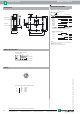
Pressing the A1 key for 2 seconds saves the selected output operating mode. The parameter assignment process is then com-
plete and the sensor returns to normal mode. If you press the A1 key briefly instead, you go to Level 2 (parameter assignment
of ultrasonic beam range).
Level 2, parameter assignment of ultrasonic beam width
The ultrasonic beam width can be adjusted to match the requirements of the application in Level 2.
Pressing the A2 key briefly will cause the possible beam widths to be selected one after the other (depending on the last beam
width to be parameterised). The functions are indicated by a flashing sequence of the red LED.
Pressing the A1 key for 2 seconds saves the selected type of beam width. The parameter assignment process is then complete
and the sensor returns to normal mode. If you press the A1 briefly instead, you go back to Level 1 (parameter assignment of
output function).
If parameterisation is not complete within 5 minutes (pressing the A1 key for 2 seconds), the sensor interrupts parameterisation
mode without changing the settings.
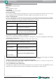
Synchronisation
The sensor is equipped with a synchronisation connection to suppress mutual interaction. If it is not turned on, the sensor works
at an internally generated cycle rate. Synchronisation of more than one sensor is possible in a number of different ways.
External synchronisation:
The sensor can be synchronised by the application of a square wave voltage externally. A synchronisation pulse on the syn-
chronisation input results in the execution of a measurement cycle. The pulse width must be greater than 100 µs. The meas-
urement cycle must be started with the falling signal edge. A Low level > 1 s or an open synchronisation input results in normal
operation of the sensor. A High level on the synchronisation input deactivates the sensor.
Two different operating modes are possible
- Multiple sensors can be controlled by the same synchronisation signal. The sensors work on synonymous cycle.
- Synchronisation pulses are sent cyclically to only one sensor each time. The sensors work in Multiplex mode.
Self synchronisation:
The synchronisation connections of up to 5 sensors with option for self-synchronisation are connected with each other. These
sensors work after turning on the operating voltage in Multiplex mode. The On delay increases depending on the number of
sensors to be synchronised. Synchronisation is possible during Teach-in and vice-versa. Sensors must be operated unsynchro-
nised to perform Teach-in of switching points.
Note:
If the option for synchronisation is not used, the synchronisation input can be connected with ground (0 V) or the sensor can be
operated with a V1 connection cable (4-pin).
Operating mode Flashing sequence of green LED A2 key
2 x normally open function
(default)
2 x normally closed func-
tion
2 switching points
n.o. (output 1) +
n.c. (output 2)
Window (output 1) +
switching point (output 2)
Beam width Flashing sequence of red LED A2 key
Narrow beam width
Average beam width
Wide beam
(default)
Pause
Pause
Pause
Pause
Pause
Pause
Pause