
User manual


RMS-D · RMS-D-RC · RMS-D-NA · RMS-D-RC-NA · RMS-D-Broad
LED status display
Color indicators Status
G
Green
Device ready
for operation
R
Red Detection active
G
Green flashing Command received
R
Red flashing Fault
R/G
Red/green
flashing
Initialization after
switching on
Detection capabilities
Direction detection Turtle mode
No direction detection
Detection of very slow-moving movements
Door closed
Door opens when a slow-moving object
approaches which would not be detected
with standard detection
Door open
The door closes if no movement is
detected within the set monitoring time.
With forward direction
detection (towards the sensor)
With backward direction
detection (away from the sensor)
Cross-traffic suppression
Little cross-traffic,
door remains closed
Monitoring time/ sensitivity
3 seconds/ decreasing
A lot of cross-traffic,
door remains closed
Monitoring time/ sensitivity
5 seconds/ constant maximum sensitivity
Immunity
5
G
2
2
5
Switch DIP switch 5. 1.
The green LED will flash.
Switch DIP switch 2.2.
Change the sensitivity of 3.
immunity using the potentiometer.
The LED displays the immunity set.
Reset DIP switch 2. 4.
The settings are saved.
Reset DIP switch 5.
Off-delay time (output)
5
G
1
1
5
Switch DIP switch 5. The green LED will flash.1.
Switch DIP switch 1.2.
Change the relay off-delay time using the 3.
potentiometer. The relay is then continually
opened and closed at the set off-delay time.
The LED changes from green to red accordingly.
Reset DIP switch 1. The settings are saved.4.
Reset DIP switch 5. 5.
0,2 s
0,5 s
1,0 s
1,5 s
2,0 s
3,0 s
4,0 s
5,0 s
Restoring default settings
5
G
4
R
4
5
Switch DIP switch 5. 1.
The green LED will flash.
Switch DIP switch 4. 2.
The red LED will flash.
Reset DIP switch 4. 3.
The sensor is reset to the
factory settings and restarted.
Reset DIP switch 5 after the 4.
initialization period has expired.
Initialization period
The hardware and software are initialized
when the operating voltage is connected.
This initialization period lasts 10 seconds.
The red/green LED will flash. Set the sensor.
Check the settings by walking the sensing area.
Additional functions can only be set during
the initialization period.
Turtle mode detection area
Door closed
5
G
3
1
1
3
5
Switch DIP switch 5. 1.
The green LED will flash.
Switch DIP switch 3. 2.
Switch DIP switch 1.3.
Change the detection area 4.
size using the potentiometer.
Reset DIP switch 1.5.
Reset DIP switch 3. 6.
The settings are saved.
Reset DIP switch 5.7.
Turtle mode detection area
Door open
5
G
3
2
2
3
5
Switch DIP switch 5. 1.
The green LED will flash.
Switch DIP switch 3.2.
Switch DIP switch 2.3.
Change the detection area 4.
size using the potentiometer.
Reset DIP switch 2.5.
Reset DIP switch 3. 6.
The settings are saved.
Reset DIP switch 5.7.
Additional functions
5
G
...
5
Remember the position of the potentiometer so that
you can reset it to the original setting if required.
During the initialization period you can switch on the additional functions mode.
In order to do this, switch DIP switch 5. The green LED will flash. Set the additional function and reset DIP switch 5.
DIP switch 6 must be UP.
Immunity
Immunity can be used to minimize interference
such as rain, vibrations and reflections.
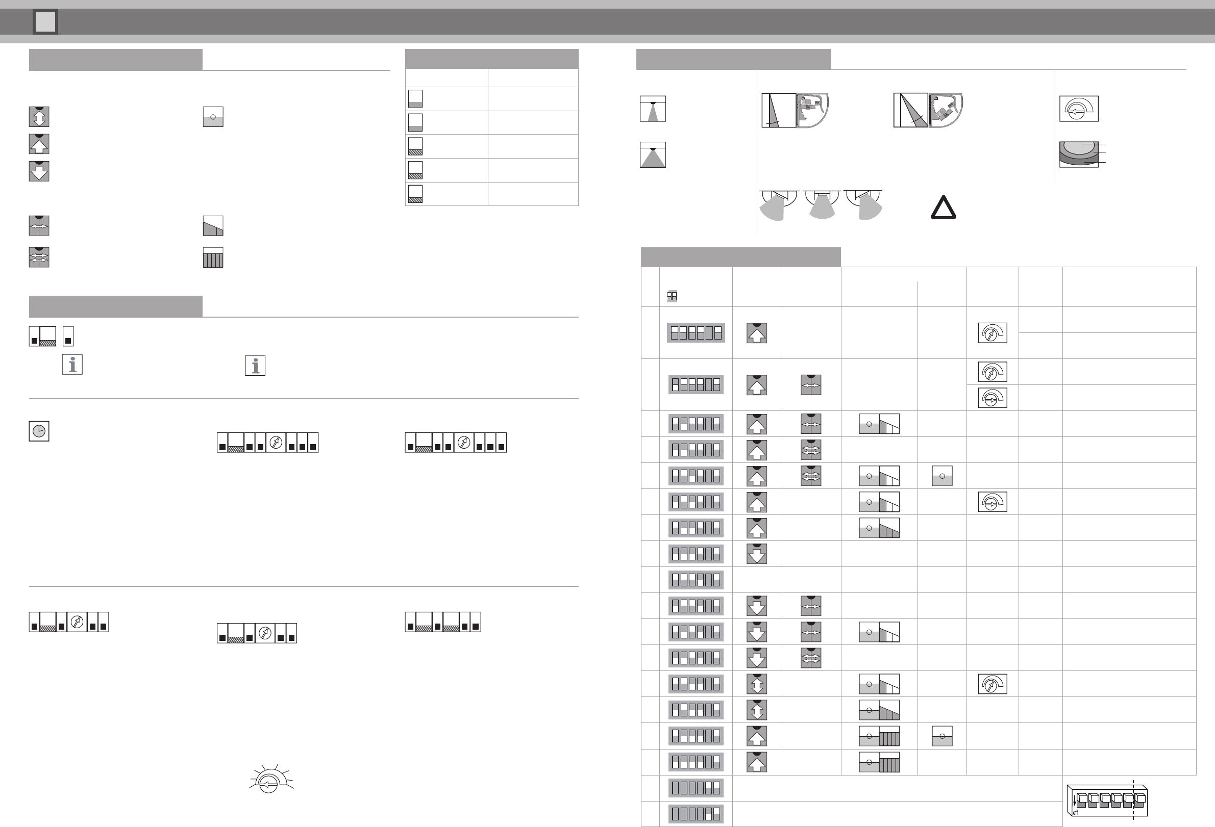
DIP switch settings
Check the settings by walking the sensing area
No.
DIP
¨=Dip switch
Direction
detection
Cross-traffic
suppression
Turtle mode
Detection
area size
Off-delay
time Application exampleOpen door
Close
door
1
SEnD SEnD SEnD
1 s Standard
0.2 s Porch
2
SEnD SEnD
0.8 s Pavement
1 s High mounting (optional, wide area)
3
SEnD
4
SEnD SEnD
5
6
SEnD SEnD
1.5 s Supermarket (optional, wide area)
7
SEnD SEnD
8
SEnD SEnD SEnD
9
SEnD SEnD SEnD
10
SEnD SEnD
11
SEnD
12
SEnD SEnD
13
SEnD SEnD
2 s Retirement home (optional, wide area)
14
SEnD SEnD
15
SEnD
16
SEnD SEnD
Relay contact when detection is active (N.O.)
1 2 3 4 5 6
DIP 6 is only available in RC versions
Relay contact when detection is passive (N.C.)
Detection area
Antenna characteristics Detection field angle Detection area size
Narrow (standard)
Width: 2.50 m
Depth: 3.00 m
0 degrees 40 degrees
min. max.
Change the size of the
detection area using
the potentiometer.
Wide (optional)
Width: 4.00 m
Depth: 2.00 m
You can change the position in steps of 5°. Holding the sensor’s base plate
by the side, move it forward and position it as required. Default setting is 15°.
The sensor’s base plate can also be inserted at an angle, i.e. up to 3 notches
to the right or left. Notches can also be removed.
Min
50 %
Max
Installation height 2.20 m
Detection area angle 30°
Sensitivity Max
Some installation situations may limit the setting options
and the functions of the sensor.
!
!
!