
User manual


RMS-D · RMS-D-RC · RMS-D-NA · RMS-D-RC-NA · RMS-D-Broad
Safety information
The device must only be operated with Safety Extra Low Voltage (SELV) which complies with the
stipulations in the safety standards based on IEC 60950. This device must only be installed and
maintained by trained, qualified persons.
In order to meet UL508 requirements, a 2.5 A slow-blow fuse should be used between the RMS
and the power supply
Radar motion sensor for approach detection at industrial doors english
!
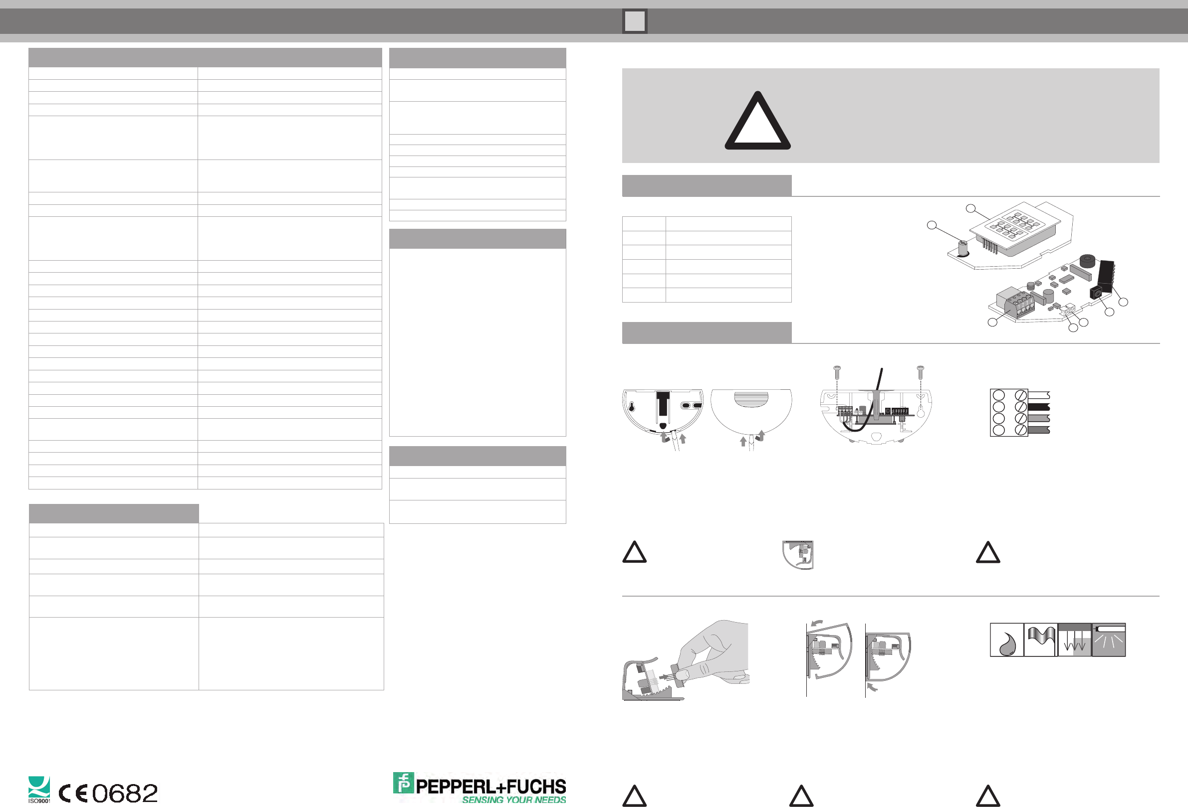
Included with delivery
Quantity Description
1 Sensor RMS-D ...
1 Connecting cable
1 Self-adhesive mounting template
2 Screws for mounting
1 Mounting instructions
Operating elements
Antenna
Potentiometer
Terminal
DIP switches
LED (red/ green)
IR receiver
IR transmitter
1
Product information
Connecting the sensor
1
2
3
4
Connect the cable to
the terminal as follows:
AC/DC supply (white)
AC/DC supply (black)
Relay contact 1 (red)
Relay contact 2 (green)
For RMS-D-NA and RMS-D-RC-NA:
In order to meet UL508 requirements,
a 2.5 A slow-blow fuse should be used
between the device and the power supply
Opening the device
Open the housing from the bottom:
Prior to installation, open the back;
following installation open the front.
Do not open the housing
from the top.
Mounting the device
Attach the self-adhesive template and drill 1.
according to the markings on the template
Pull the cable through the relevant opening.2.
Use screws to fasten the base plate 3.
(screws are in the housing).
Can be mounted on the ceiling
using RMS Weather Cap
(see accessories).
!
Installation
Installation information
Protect the sensor from the rain*.•
Avoid placing moving objects in the •
detection area (fans, plants, trees, etc.).
Mount the sensor only behind suitable •
covers. Mechanically moving drive
components could affect the sensor.
There should be no fluorescent lights •
within the detection area.
Installing the RMS Weather Cap is
recommended (see Accessories).
Replacing the cover
click
Insert the cover on the top
and press down until it engages.
Before switching on the device,
remove all objects from the
door area that do not normally
belong there.
Replacing the antenna
Select the antenna for a wide 1.
or narrow detection area.
Remove the antenna carefully 2.
using two fingers.
Insert the new antenna.3.
Do not touch any
electronic components.
Do not use metal tools.
!
!
!
!
World Headquarters
Pepperl+Fuchs GmbH . Mannheim . Germany
E-mail: FA-info@de.pepperl-fuchs.com
USA Headquarters
Pepperl+Fuchs Inc . Twinsburg . USA
E-mail: FA-info@us.pepperl-fuchs.com
Asia Pacific Headquarters
Pepperl+Fuchs Pte Ltd . Singapore 139942
E-mail: FA-info@sg.pepperl-fuchs.com
www.pepperl-fuchs.com
Technical data
Operating principle
Microwave module
Detection speed
Min. 0.1 m/s
Approvals
CE
Detection field angle
0 - 40° in 5° steps
Sensing range
at installation height of 2200 mm
and 30° angle,
2000 x 4000 mm (d x w)
RMS-D-Broad: 3000 x 2500 mm (d x w)
Operating frequency
24.15 GHz - 24.25 GHz K band
FCC (NA version):
24.075 GHz – 24.175 GHz K band
Operating mode
Microwave motion sensor
Function display
Red/ green LED
Operating elements
DIP switch for operating mode selection:
direction detection, cross-traffic suppression,
turtle mode, output mode, sensitivity adjustments,
adjustments for off-delay time
Operating voltage
12 - 36 V DC/ 12 - 28 V AC
Current consumption
< 50 mA at 24 V DC
Power consumption
< 1 W
Switching type
Normally open/normally closed
Signal output
Relay, 1 N.O. contact
Switching voltage
Max. 48 V AC / 48 V DC
Switching current
Max. 0.5 A AC/ 1 A DC
Switch power
Max. 24 W/ 60 VA
Off-delay time
0.2 s - 5 s, adjustable (factory setting 1 s)
Ambient temperature
-20° C to 60° C/ 253 - 333 K
Relative humidity
Max. 90 %, not condensing
Installation height
Max. 4000 mm
Degree of protection
IP 54
Connection
4-pin plug-in screw terminals,
5 m connecting cable supplied
Housing material
ABS, anthracite
Weight
120 g
Transmitter radiated power
< 20 dBm
Dimensions without mounting brackets
123 mm (w) x 65 mm (h) x 57 mm (d)
Troubleshooting
Fault Corrective Action
Door is detected. Reduce the sensitivity.
Pivot the sensor further forward.
LED not lit up.
No power supply, device not functioning.
Sensor responds to very slight interference
such as rain,
Increase immunity,
decrease size of detection area.
Potentiometer does not respond Operation by remote control is activated.
Push DIP switch 6 UP.
Remote control does not respond Operation with DIP switch and potentiometer
is activated. Push DIP switch 6 DOWN.
Device is locked. Switch the operating voltage
off and on again. Sensor can be configured for
30 minutes without code.
Check the remote control battery.
DOCT-1544A
Pepperl+Fuchs GmbH is certified under ISO 9001. Part no. 215075 09/2010
Default settings
Function
Setting
DIP switches Switches 1-5: up
Switch 6: down
Detection area size Potentiometer:
remote control
medium setting: 8
Detection field angle 15°
Direction detection Forward
Off-delay time 1 s
Relay contact Active
Cross-traffic
suppression
Potentiometer: from
remote control: 1
Immunity 4
Turtle mode Off
Accessories
RMS remote control
Remote control operation
RMS Weather Cap
Mounting set and
weather-proof cap
RMS antenna broad
Antenna for a wide
detection area
Conformity
EC conformity: The products RMS-D, RMS-D-
RC and RMS-D-Broad are compliant with
Directive 1999/5/EC, device class 1 and the
following harmonized standards EN 62311,
EN 60950-1, EN 301 489-1, EN 301489-3,
EN 300 440-2
A complete version of the declaration of confor-
mity is available for download at
www.pepperl-fuchs.com.
US conformity: The products RMS-D-NA and
RMS-D-RC-NA are compliant with
FCC regulations, part 15.
ATTENTION! EC-compliant devices must not be
sold in the US and US-compliant devices must
not be sold in Europe!
for RMS-D, RMS-D-RC and RMS-D-Broad