
Datasheet
Inductive positioning system PMI210-F110-IU-V1
2
Release date: 2012-05-14 13:27 Date of issue: 2016-05-03 191142_eng.xml
Germany: +49 621 776 4411Pepperl+Fuchs Group
Refer to “General Notes Relating to Pepperl+Fuchs Product Information”.
USA: +1 330 486 0001 Singapore: +65 6779 9091
www.pepperl-fuchs.com fa-info@us.pepperl-fuchs.com fa-info@sg.pepperl-fuchs.com
fa-info@de.pepperl-fuchs.com
Instruction manual
• Security advice
• Sensor Properties
The inductive positioning system F110 provides both, a current and voltage signal at the outputs, which is
proportional to the position of the attenuating element.
Output signals: 4 mA ... 20 mA and 0 V ... 10 V
• Attenuating element
The inductive position encoding system F110 is optimally
adjusted to the geometry of the attenuating elements we offer
(see accessories, below).
• Installation and operation
Notes on installation
- A flush installation is possible.
- Fixation and installation of the positioning system F110 is carried out by
the use of t-slides. This provides a flexible adaptation to the field situation.
- The distance between the measuring field (bordered area at the front of
the sensor) and the fixing base or fixing element of the attenuating ele-
ment must at least be 6 mm.
• Notes on operation
The sensor accuracy can be guaranteed, when the spacing between attenuating element and sensor is
within an interval of 1 ... 6 mm.
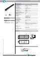
Pinout
Accessories
BT-F110-G
Damping element for F110 housing sensors; front screw holes
BT-F110-W
Damping element for F110 housing sensors; lateral screw holes
V1-G-2M-PVC
Female cordset, M12, 4-pin, PVC cable
MH-F110
Mounting bracket for mounting F110 series sensors
This product must not be used in applications, where safety of persons
depend on the correct device function.
This product is not a safety device according to EC machinery directive.
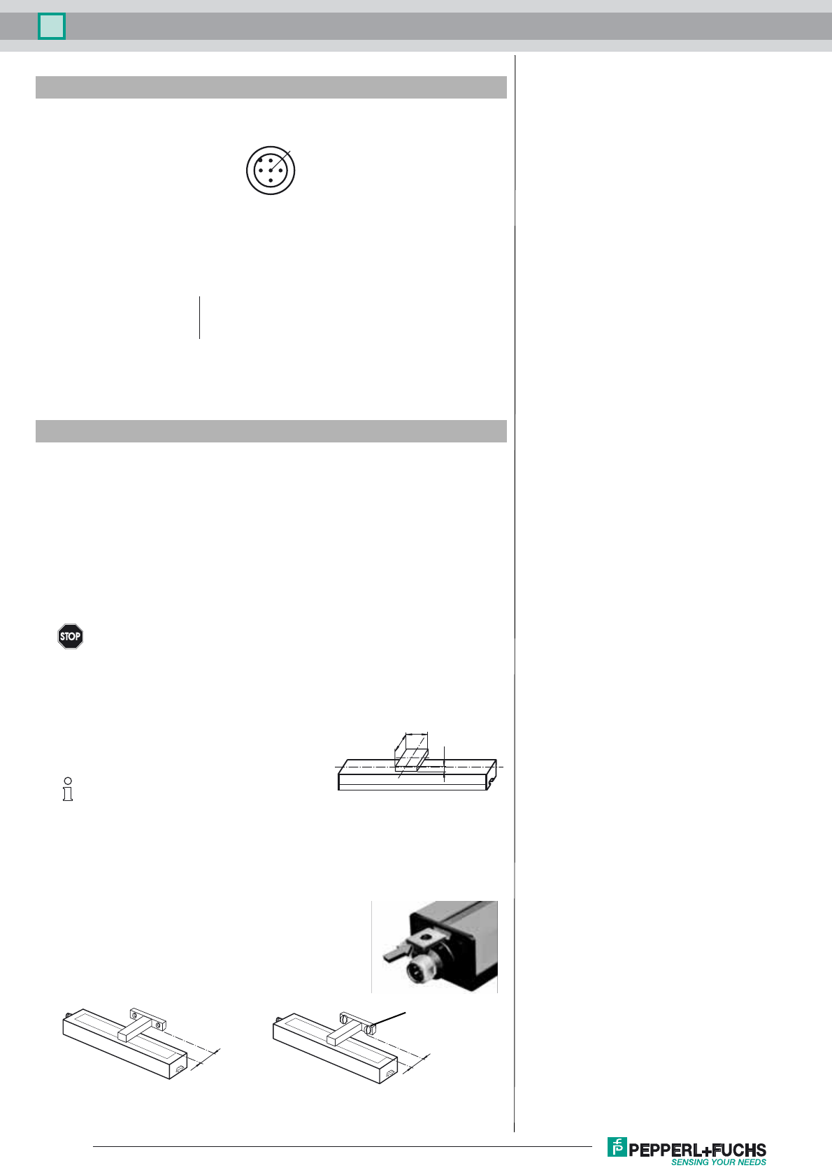
When using your own attenuating elements, you
must ensure that the active surface of the attenua-
ting element has a width of exactly 13 mm and
overlaps the entire sensor width (41 mm).
A different width has a direct impact on the achie-
vable resolution and accuracy of the system.
Spacing between sensor and attenuating element is from 0 ... 6 mm.
Sensing accuracy is guaranteed between 1 ... 6 mm..
1
3
4
5
2
1 BN
2 WH
3 BU
4 BK
Wire colors in accordance with EN 60947-5-2
(brown)
(white)
(blue)
(black)
Warning
≥ 4
13
≥ 41
j
Note
6
6
screw head