
Datasheet

Subject to reasonable modifications due to technical advances. Copyright Pepperl+Fuchs, Printed in Germany
Pepperl+Fuchs Group • Tel.: Germany +49 621 776-0 • USA +1 330 4253555 • Singapore +65 67799091 • Internet http://www.pepperl-fuchs.com
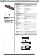
Inductive positioning system PMI104-F90-IE8-V15
2
Release date: 2012-05-30 16:55 Date of issue: 2012-05-30 191138_eng.xml
Operating instructions
• Safety information
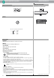
• Sensor versions
The F90 linear position measurement system is available in 2 versions.
In the PMI...-F90-IU-V1 version, the position measuring system transmits current and voltage signals pro-
portional to the position of the damping element at the outputs.
The PMI...-F90-IE8-V15 version offers a current signal as well as the option of teaching in two switching
points directly at the sensor independently of one another at the press of a button, which is then indicated
on two switching outputs. Two additional LEDs indicate the output states of the two switching outputs.
Version PMI…-F90-IU-V1
Output signals: 4 mA ... 20 mA and 0 V ... 10 V
Version PMI…-F90-IE8-V15
Output signals: 4 mA ... 20 mA and 2 programmable switching amplifiers
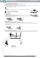
• Programming the PMI…-F90-IE8-V15
The rear of the PMI...-F90-IE8-V15 sensor has two small, slightly recessed push buttons for programming
the switching points. The buttons are marked "teach in" and S1 for switching point S1 and S2 for switching
point S2.
To teach in a switching point, proceed as follows:
- The position detection damping element must be placed at the relevant position, i.e. the switching point
that you wish to teach in.
Electrical Connection
Pinout
Accessories
BT-F90-W
Damping element for F90 sensors; lateral screw holes
MH-F90
Mounting bracket for mounting of F90 sensors
V15-G-2M-PVC
Cable socket, M12, 5-pin, PVC cable
V15-W-2M-PVC
Cable socket, M12, 5-pin, PVC cable
This product may not be used in applications where personal safety
depends on the function of the device.
This product is not a safety component as described in EU Machinery Direc-
tive.
Only the current output or the voltage output may be used. The unused output must remain
load free.
+ UB
- UB
1
5
2
4
3
I
Q S1
Q S2
4-20 mA
IE8
1
3
4
5
2
1 BN
2 WH
3 BU
4 BK
5 GY
Wire colors in accordance with EN 60947-5-2
(brown)
(white)
(blue)
(black)
(gray)
Warning
Note
Additional Information
≥ 4
8
≥ 18
dimensions for the target object:
Linearity range
Measuring range
10 V/20 mA
0 V/4 mA