
Datasheet

Photoelectric
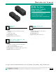
M1K Series Mini Limit Switch Style
Photoelectric Sensors
Pepperl+Fuchs Inc. • 1600 Enterprise Parkway • Twinsburg, Ohio 44087-2245 • www.am.pepperl-fuchs.com
Telephone (330) 486-0001 • FAX (330) 405-4710 • E-Mail: sales@us.pepperl-fuchs.com
®
PEPPERL+FUCHS
509
ON
OFF
1 2 3 4 5
1.5kHz
200Hz
20ms
0ms
dynamic
static
frequency 2
frequency 1
normally closed
normally open
S1 Switching Frequency
S2 Pulse Lengthener
S3 Weak Signal Indicator and Output
S4 Pulse Frequency
S5 Switch Output
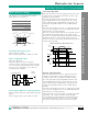
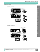
Mini Limit Switch Series Programming
Switching Frequency (S1)
(OFF=200Hz, ON=1.5kHz)
The weak signal output is not available at 1.5kHz.
Pulse Lengthener (S2)
(OFF=0ms, ON=20ms)
The pulse lengthener activates an impulse
extension of 20ms. This may be beneficial when the
sensor is used with a programmable logic controller
and the sensor’s output pulses are too fast to be
recognized by the controller.
DIP switches are accessible when the terminal
compartment cover is removed.
S2-Impulse Extension t
v
t
v
t
v
t
v
t
v
Impulse
Extension
no
yes
1
0
1
0
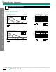
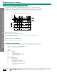
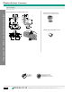
Static Operating Mode
This mode should be chosen for applications that have a fixed
sensing distance and position. Web break detection or edge
guiding are typical examples.
The weak signal indicator (red LED) will flash and the weak
signal output will turn ON as the target enters the sensing
range. When the target is fully within the sensing range, the
weak signal output will turn OFF and the red LED will stop
flashing.
The weak signal output can be used as an alignment aid. If the
sensor goes out of alignment, the weak signal output will turn
ON, indicating a need for adjustment.
If the lens gets dirty, when the light level received falls between
the minimum and maximum points of the stability control
range, the weak signal output will turn ON and the red LED will
flash. When the lens is cleaned and the light level received
returns to normal, the weak signal output will turn OFF and the
red LED will stop flashing.
Static Mode of Operation for the Diffused Mode M1K sensors
Switching Hysteresis
Light received
by sensor
Switch on point Switch off point
Stability Control
Range
t
t
t
t
Switch Output
(Normally Open)
LED Yellow
DUAL-LED
Green - Operating Voltage
Red - Stability Control
Weak
Signal
Output
Weak Signal Indicator and Ouput (S3)
(OFF=Static Operating Mode, ON=Dynamic Operating
Mode)
The weak signal output is not available at 1.5kHz
Dynamic Operating Mode
This mode should be chosen for use with targets that have
variable sensing distances or high switching frequencies.
Counting of gear teeth or positioning are typical examples.
The weak signal indicator (red LED) will flash and the weak
signal output will turn ON as the target enters the sensing
range. When the target is fully within the sensing range, the
weak signal output will turn OFF and the red LED will stop
flashing.
The weak signal output can be used as an alignment aid. If the
sensor goes out of alignment, the weak signal output will turn
ON, indicating a need for adjustment.
In dynamic mode, the sensor examines each full cycle (switch
output OFF – ON – OFF) to determine whether the light
received falls between the minimum and maximum points of
the stability control range for the cycle. As long as the light
level stays out of this range for the cycle, the weak signal
DIP Switch Settings