
- Pep Smart I/O User's Manual
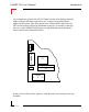
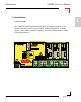
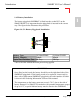
Table Of Contents
- Preface.pdf
- Introduction.pdf
- Table of Contents
- General Information
- Weights & Measures
- 1.1 Product Overview
- 1.2 Ordering Information
- 1.3 Product Information
- 1.4 Installation
- 1.4.1 Overview
- 1.4.2 SMART I/O Module Installation
- 1.4.3 RJ45 Telephone Connector Installation
- 1.4.4 Screw Terminal Block Installation
- 1.4.5 Battery Installation
- 1.5 ISaGRAF-Installation
- 1.5.1 Before Installing
- 1.5.2 Installation of the ISaGRAF for Windows Workbench
- 1.5.3 Installation of PEP Library Functions
- 1.5.4 Demo Application
- Table of Contents
- SM-BASE.pdf
- Table of Contents
- 2. SMART-BASE
- 2.1 Specifications
- 2.2 Board Overview
- 2.3 Functional Description
- 2.4 Configuration
- 2.4.1 Jumper J1: Boot Selection (Pin Connector)
- 2.4.2 Jumper J6: LED Function (Pin Connector)
- 2.5 Pinouts
- 2.5.1 SMART Module Piggyback Connectors
- 2.5.2 Screw Terminal Pinouts
- 2.5.3 Timer I/O Screw Terminal (SCR1)
- 2.5.4 Supply Screw Terminals (SCR2)
- 2.5.5 RS232 Telephone Connector (BU1)
- 2.5.6 RS485 D-Sub Connector for Half-Duplex Operation (Profibus)
- 2.5.7 SPI Connector (ST7)
- 2.6 ‘C’ Programming
- 2.6.1 SMART-BASE Library
- 2.6.2 SMTselIn
- 2.6.3 SMTsettout
- 2.6.4 SMTpre
- 2.6.5 SMTstasto
- 2.6.6 SMTrd
- 2.6.7 SMTtin
- 2.6.8 SMTstat
- 2.6.9 SMTout
- 2.6.10 SMLed
- 2.6.11 SMwdon
- 2.6.12 SMwdtrig
- 2.6.13 SMwdoff
- 2.7 ISaGRAF Programming
- 2.7.1 The ISaGRAF Board Parameters
- 2.7.2 The ISaGRAF Operate Calls
- 2.8 Flash Utility
- Table of Contents
- SM-EXT.pdf
- Digital.pdf
- Table of Contents
- 4. Digital Modules
- 4.1 SM-DIN1
- 4.1.1 Introduction
- 4.1.2 Specifications
- 4.1.3 Front Panel Layout
- 4.1.4 Board Overview
- 4.1.5 Functional Description
- 4.1.6 Configuration
- 4.1.7 Pinouts
- 4.1.8 ‘C’ Programming
- 4.1.8.1 SM-DIN1 Library
- 4.1.8.2 SMDIN1Init
- 4.1.8.3 SMDIN1DeInit
- 4.1.8.4 SMDIN1Get
- 4.1.9 ISaGRAF Programming
- 4.1.9.1 The ISaGRAF Board Parameters
- 4.1.9.2 The ISaGRAF Operate Calls
- 4.2 SM-DOUT1
- 4.2.1 Introduction
- 4.2.2 Specifications
- 4.2.3 Front Panel Layout
- 4.2.4 Board Overview
- 4.2.5 Functional Description
- 4.2.6 Configuration
- 4.2.7 Pinouts
- 4.2.8 ‘C’ Programming
- 4.2.8.1 SM-DOUT1 Library
- 4.2.8.2 SMDOUT1Init
- 4.2.8.3 SMDOUT1DeInit
- 4.2.8.4 SMDOUT1Get
- 4.2.8.5 SMDOUT1Set
- 4.2.9 ISaGRAF Programming
- 4.2.9.1 The ISaGRAF Board Parameters
- 4.2.9.2 The ISaGRAF Operate Calls
- 4.3 SM-REL1
- 4.3.1 Introduction
- 4.3.2 Specifications
- 4.3.3 Front Panel Layout
- 4.3.4 Board Overview
- 4.3.5 Functional Description
- 4.3.6 Configuration
- 4.3.7 Pinouts
- 4.3.8 ‘C’ Programming
- 4.3.8.1 SM-REL1 Library
- 4.3.8.2 SMREL1Init
- 4.3.8.3 SMREL1DeInit
- 4.3.8.4 SMREL1Reset
- 4.3.8.5 SMREL1GetRly
- 4.3.8.6 SMREL1SetRly
- 4.3.8.7 SMREL1GetLed
- 4.3.8.8 SMREL1SetLed
- 4.3.8.9 SMREL1GetExtVcc
- 4.3.9 ISaGRAF Programming
- 4.3.9.1 The ISaGRAF Board Parameters
- 4.3.9.2 The ISaGRAF Operate Calls
- Table of Contents
- Analog.pdf
- Table of Contents
- 5. Analog Modules
- 5.1 SM-DAD1
- 5.1.1 Introduction
- 5.1.2 Specifications
- 5.1.3 Front Panel Layout
- 5.1.4 Board Overview
- 5.1.5 Functional Description
- 5.1.5.1 Input Circuitry
- 5.1.5.2 Output Circuitry
- 5.1.6 Configuration
- 5.1.7 Pinouts
- 5.1.8 ‘C’ Programming
- 5.1.8.1 SM-DAD1 Library
- 5.1.8.2 SMDAD1Init
- 5.1.8.3 SMDAD1DeInit
- 5.1.8.4 SMDAD1GetVRaw
- 5.1.8.5 SMDAD1GetV
- 5.1.8.6 SMDAD1PutVRaw
- 5.1.8.7 SMDAD1PutV
- 5.1.8.8 SMDAD1SetLed
- 5.1.8.9 SMDAD1ClrLed
- 5.1.9 ISaGRAF Programming
- 5.1.9.1 The ISaGRAF Board Parameters
- 5.1.9.2 The ISaGRAF Operate Calls
- 5.2 SM-PT100
- 5.2.1 Introduction
- 5.2.2 Specifications
- 5.2.3 Front Panel Layout
- 5.2.4 Board Overview
- 5.2.5 Functional Description
- 5.2.6 Configuration
- 5.2.7 Pinouts
- 5.2.8 ‘C’ Programming
- 5.2.8.1 SM-PT100 Library
- 5.2.8.2 SMADCInit
- 5.2.8.3 SMADCCalibrate
- 5.2.8.4 SMADCSetCyclicCalib
- 5.2.8.5 SMADCSetSensorType
- 5.2.8.6 SMADCGetSensorType
- 5.2.8.7 SMADCSetPrecision
- 5.2.8.8 SMADCGetPrecision
- 5.2.8.9 SMADCSetMode
- 5.2.8.10 SMADCGetMode 5-47
- 5.2.8.11 SMADCSetSignal
- 5.2.8.12 SMADCSetGain
- 5.2.8.13 SMADCGetGain
- 5.2.8.14 SMADCEnableRead
- 5.2.8.15 SMADCEnableConversion
- 5.2.8.16 SMADCReadRaw
- 5.2.8.17 SMADCReadConverted
- 5.2.8.18 SMADCDeinit
- 5.2.9 ISaGRAF Programming
- 5.2.9.1 The ISaGRAF Board Parameters
- 5.2.9.2 The ISaGRAF Operate Calls
- 5.3 SM-THERM
- 5.3.1 Introduction
- 5.3.2 Specifications
- 5.3.3 Front Panel Layout
- 5.3.4 Board Overview
- 5.3.5 Functional Description
- 5.3.6 Configuration
- 5.3.7 Pinouts
- 5.3.8 ‘C’ Programming
- 5.3.8.1 SM-THERM Library
- 5.3.8.2 SMADCInit
- 5.3.8.3 SMADCCalibrate
- 5.3.8.4 SMADCSetCyclicCalib
- 5.3.8.5 SMADCSetSensorType
- 5.3.8.6 SMADCGetSensorType
- 5.3.8.7 SMADCSetPrecision
- 5.3.8.8 SMADCGetPrecision
- 5.3.8.9 SMADCSetMode 5-75
- 5.3.8.10 SMADCGetMode
- 5.3.8.11 SMADCSetSignal
- 5.3.8.12 SMADCSetGain
- 5.3.8.13 SMADCGetGain
- 5.3.8.14 SMADCEnableRead
- 5.3.8.15 SMADCEnableConversion
- 5.3.8.16 SMADCReadRaw
- 5.3.8.17 SMADCReadConverted
- 5.3.8.18 SMADCDeinit
- 5.3.9 ISaGRAF Programming
- 5.3.9.1 The ISaGRAF Board Parameters
- 5.3.9.2 The ISaGRAF Operate Calls
- 5.4 SM-ADC1
- 5.4.1 Introduction
- 5.4.2 Specifications
- 5.4.3 Front Panel Layout
- 5.4.4 Board Overview
- 5.4.5 Functional Description
- 5.4.5.1 Input Circuitry
- 5.4.6 Configuration
- 5.4.7 Pinouts
- 5.4.8 ‘C’ Programming
- 5.4.8.1 SM-ADC1 Library
- 5.4.8.2 SMADC1Init
- 5.4.8.3 SMADC1GetVRaw
- 5.4.8.4 SMADC1GetV
- 5.4.8.5 SMADC1SetLed
- 5.4.8.6 SMADC1ClrLed
- 5.4.8.7 SMADC1DeInit
- 5.4.9 ISaGRAF Programming
- 5.4.9.1 The ISaGRAF Board Parameters
- 5.4.9.2 The ISaGRAF Operate Calls
- 5.5 SM-DAC1
- 5.5.1 Introduction
- 5.5.2 Specifications
- 5.5.3 Front Panel Layout
- 5.5.4 Board Overview
- 5.5.5 Functional Description
- 5.5.5.1 Output Circuitry
- 5.5.6 Configuration
- 5.5.7 Pinouts
- 5.5.8 ‘C’ Programming
- 5.5.8.1 SM-DAC1 Library
- 5.5.8.2 SMDAC1Init
- 5.5.8.3 SMDAC1OpenLoop
- 5.5.8.4 SMADAC1Operate
- 5.5.8.5 SMDAC1StandBy
- 5.5.8.6 SMDAC1PutVRaw
- 5.5.8.7 SMDAC1PutV
- 5.5.8.8 SMDAC1SetLed
- 5.5.8.9 SMDAC1ClrLed
- 5.5.8.10 SMDAC1DeInit
- 5.5.9 ISaGRAF Programming
- 5.5.9.1 The ISaGRAF Board Parameters
- 5.5.9.2 The ISaGRAF Operate Calls
- Table of Contents
- Comms.pdf
- Table of Contents
- 6. Communications Modules
- 6.1 SM-RS232 6
- 6.1.1 Introduction
- 6.1.2 Specifications
- 6.1.3 Front Panel Layout
- 6.1.4 Board Overview
- 6.1.5 Functional Description
- 6.1.6 Configuration
- 6.1.7 Pinouts
- 6.1.8 ISaGRAF Programming
- 6.1.8.1 The ISaGRAF Board Parameters
- 6.1.8.2 The ISaGRAF Operate Calls
- 6.1.9 OS-9 Programming
- 6.2 SM-SSI
- 6.2.1 Introduction
- 6.2.2 Specifications
- 6.2.3 Front Panel Layout
- 6.2.4 Board Overview
- 6.2.5 Functional Description
- 6.2.6 SSI Operation
- 6.2.7 Register Description
- 6.2.7.1 Control Register
- 6.2.7.2 CTRL1 Register
- 6.2.7.3 CTRL2 Register
- 6.2.7.4 CTRL3 Register
- 6.2.7.5 Compare Register
- 6.2.7.6 Identification Register
- 6.2.7.7 Status Register
- 6.2.7.8 STAT1 Register
- 6.2.7.9 STAT2 Register
- 6.2.7.10 Data Register
- 6.2.8 MATCH Function
- 6.2.9 Tested Sensors
- 6.2.10 Configuration
- 6.2.11 Pinouts
- 6.2.12 ‘C’ Programming
- 6.2.12.1 SM-SSI Library
- 6.2.12.2 SMSSIInit
- 6.2.12.3 SMSSIDeInit
- 6.2.12.4 SMSSISetSetPoint
- 6.2.12.5 SMSSISetCtrlReg
- 6.2.12.6 SMSSIGetStatus
- 6.2.12.7 SMSSIGetData
- 6.2.13 ISaGRAF Programming
- 6.2.13.1 The ISaGRAF Board Parameters
- Table of Contents
SMART I/O User’s Manual
March 12, 1996
©1996 PEP Modular Computers GmbH
Page 1 - 12
Introduction
An on-board fuse protects the 24V DC input circuitry from damage through
higher voltages than those expected or AC voltages being inadvertently
applied to the system. This fuse, should it be assumed defect (the Power In
LED on the housing will not be illuminated), may be accessed by removing
the cover of the SMART-BASE and accessing the holder on the left-hand
side as shown in the illustration below.
In the event of a blown fuse, replace it with the same size and type as the one
installed.
D3
D4
C6
C7
C1
SCR2
123
R77
F1 0.60A M